
Baddeley B2V2 Head Pogo Bracket
Obliczymy ostateczną cenę na podstawie wybranego pliku. Sprawdzisz ją i zaakceptujesz przed płatnością.
Zapisane na tym urządzeniu.

These parts can be used to mount an alternative pogo connector between the head and head lift mech of the Baddeley B2V2.
- Ocena
- 0 / 5
- Polubienia
- 4
- Pobrania
- 28
- Wydruki
- 0
- Wyświetlenia
- 216
- Oceny
- 0
Aktualizacja u źródła:
Informacje o modelu
- Źródło
- Printables
- Kategoria
- RC & Robotics
- Licencja
- Creative Commons — Attribution
For my Baddeley B2V2, I was not able to find the exact pogo connector intended to be used in the small slot available in the stock interface between the head lift mech and the head itself. Additionally, many of the pogo connectors that I have found have very small pins that require careful and precise soldering and even after connecting the wires are not well arranged to allow for the tight turns and bends required for the wiring to sit flush within the head.
Pogo Connectors Used
After trying several different pogo connectors, I came across these connectors that have several key advantages that make them ideal for this connection:
- These connectors have 90 degree pins that allow the connectors to sit flush against the head plate - no tight bends in the wire are required.
- The pins are long enough that you can simply crimp a female Dupont connector to the wire and cover with heat shrink tubing to create a strong, reliable connection. No soldering required!
- These connectors come in configurations from 2 to 5 pins, but all have the same size housing and thus can be swapped out without the need to print alternative mounting brackets.
- The pins themselves are able to be rotated around, providing additional placement flexibility.
Additional Hardware Used
The mounting holes provided are sized for M3 flathead hardware of various lengths. The top plate of the head is thin - so be careful not to drill all the way through. 5-6mm hardware is about all you can use for the thinner parts.
Preparing The Connectors
When you receive the connectors, the angled pins will be oriented in such a way that when the two connectors are mated, the pins will all point in the same direction. You will want to rotate the pins on one of the connectors to point AWAY from the pins on the other connector. The pins will bend slightly so they can “lift” over their neighbor. Once complete, the pins can be further flattened slightly to ensure as low profile an installation as possible.
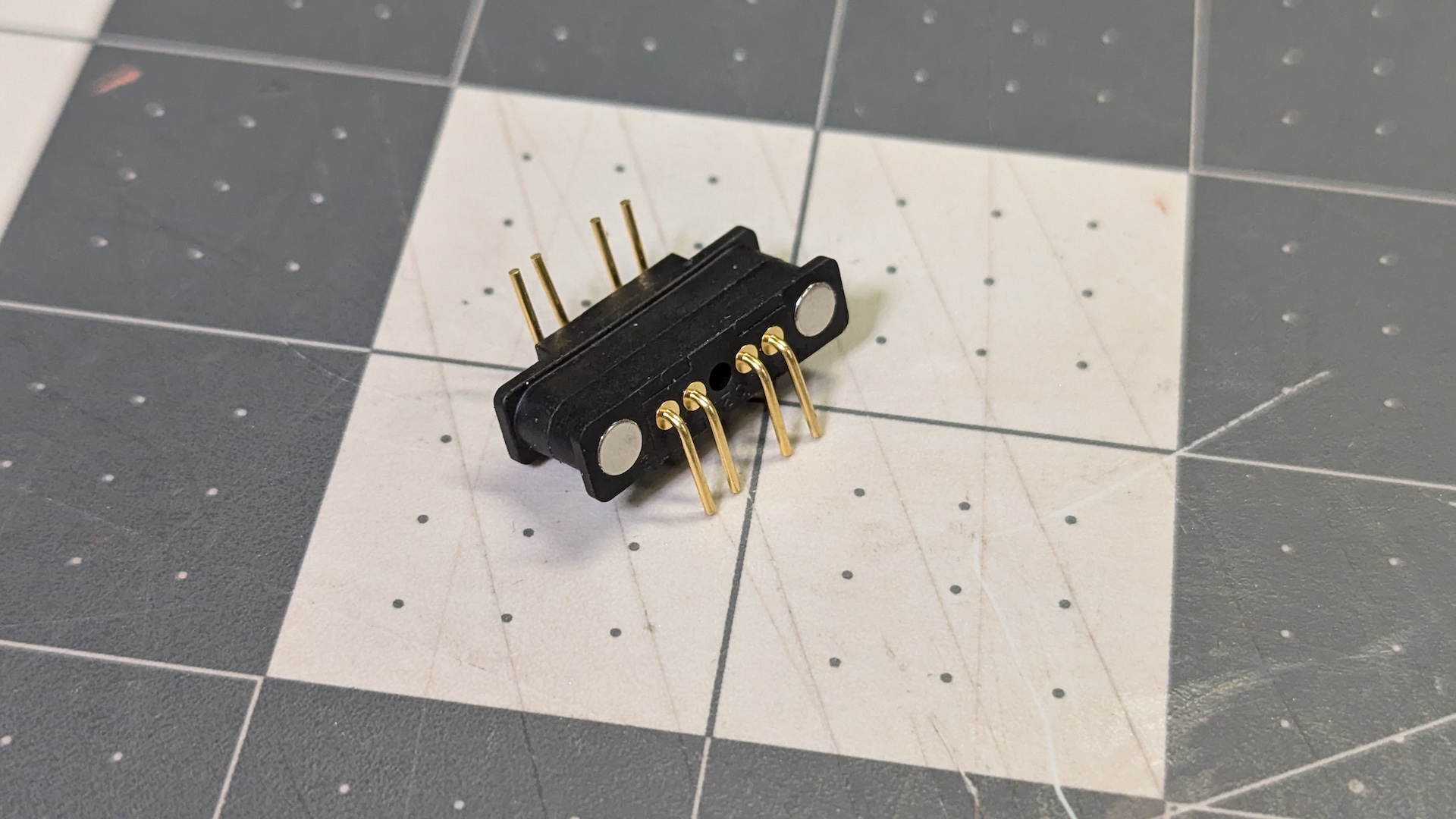
For the wires, I used 22 gauge silicone-jacketed hookup wire with female Dupont connectors crimped to the ends and heat-shrink tubing applied for insulation. Thinner wire can also work well, but I find 22-26 gauge easiest to use with Dupont connectors. Make sure the wires are firmly secured to the pins.
Preparing The Head (HatTop-Plate.3mf)
In order to ensure that the connector can sit completely flush against the inside of the head, the narrow channel that runs outward to carry the wiring beyond the lazy susan needs to be widened sufficiently at the point where the connector will sit so that the pins can descend into the channel unimpeded. The channel can then be gently tapered to its original width. This can easily be done with any rotary tool. This may not be required for 2 or 3 pin connectors, but was necessary for the 4 pin version.
The Head Connection
PogoBracketA is the housing that will surround the male connector. It is designed to hold the connector loosely so that it can shift position slightly to ensure a good connection with the head lift plate. With the bracket held firmly against the inside of the curved ring on the plate, mark and drill shallow holes for the M3 screws that will hold it in place.
It is important that this bracket be placed firmly against the inside ring so that placement is correct.
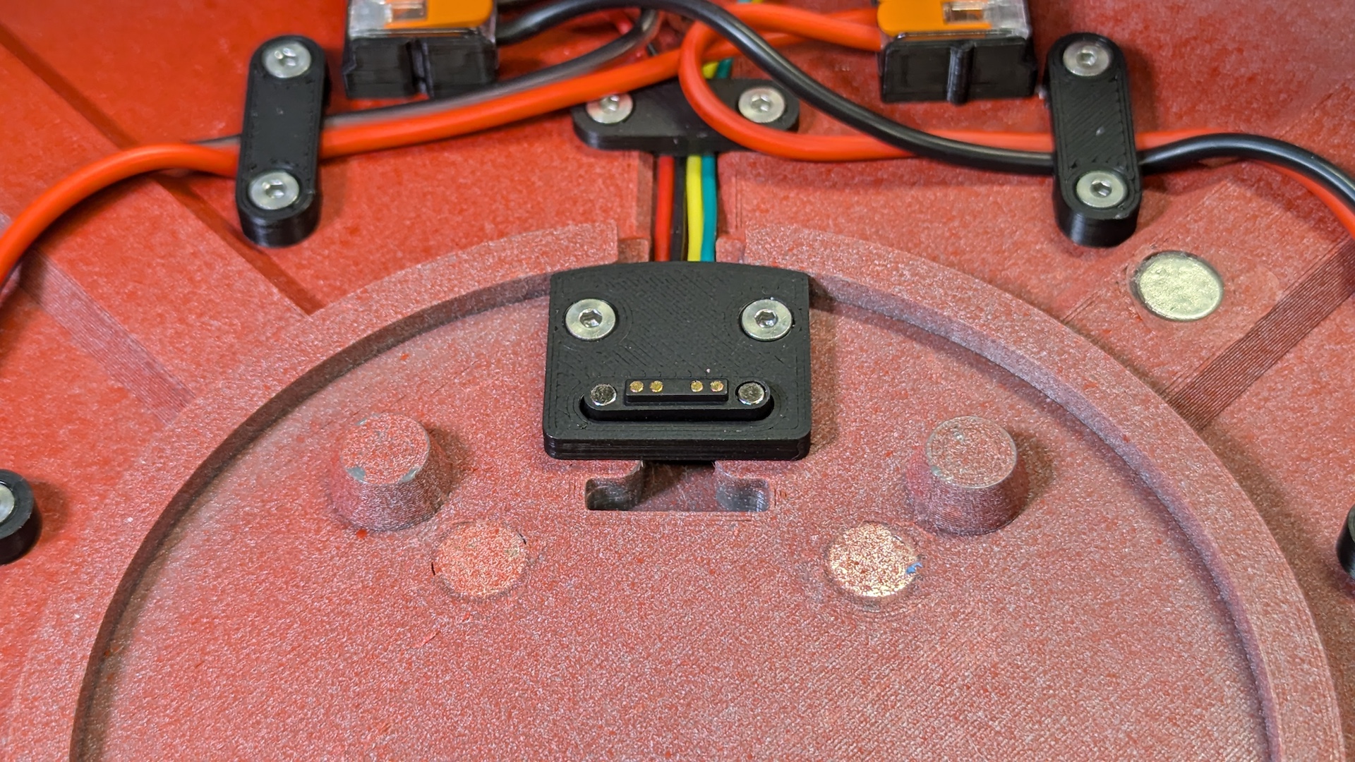
Once installed, make sure the connector is free to move about a little bit. This will provide a little bit of forgiveness when making the connection.
WireClamp is an extra piece provided that can be fastened across the channel outboard of the circular ring using the existing holes. It should provide some additional strain relief for the wiring from the connector.
The Head Lift Mechanism Connection
For the female connector, a two-part bracket is used. This bracket should hold the connector snugly in place with little to no movement.
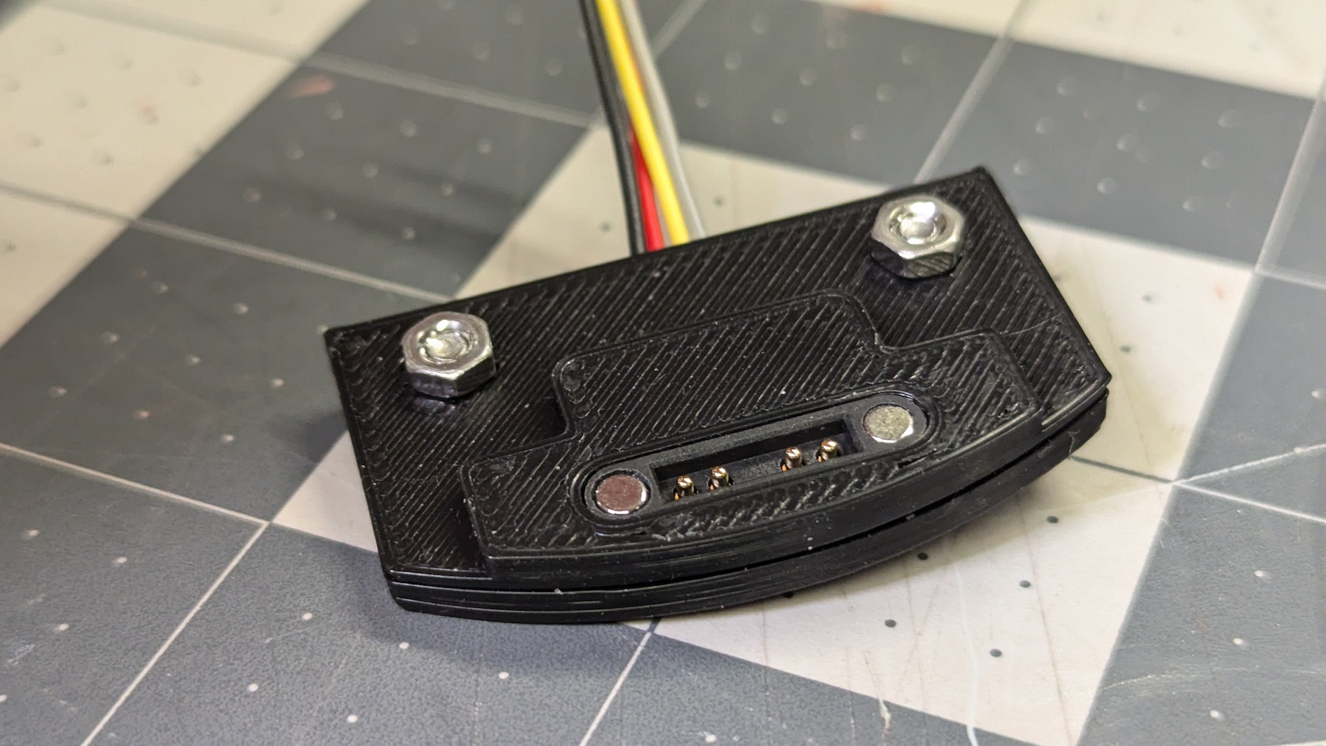
First, insert the female connector from the flat side of PogoBracketB1. Once fully inserted, the connecting surface should sit flush in the raised area on the opposite side of the bracket (the nuts visible in the photos are not needed for actual installation - they were only needed for the photo).
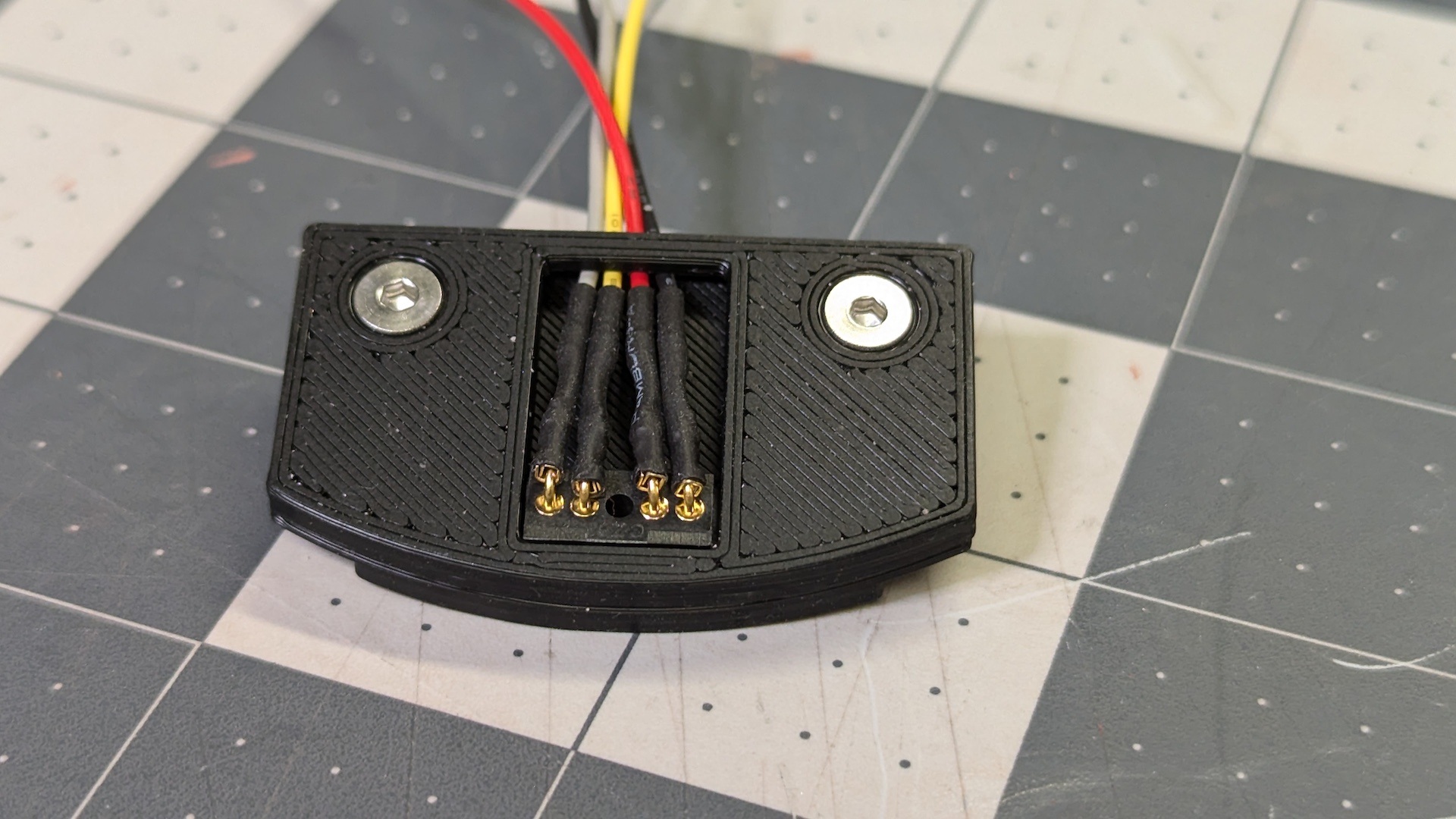
Flip the assembly over and place PogoBracketB2 in place around the connector. The recesses in PogoBracketB2 should fit snugly around the base of the connector, and the wiring should be held in place by the raised crossbar.
This assembly can then be attached to the bottom surface of TopHeadPlate.3mf from the updated files for the Head Mech of B2V2. The raised area of PogoBracketB1 should nestle perfectly into place, ensuring proper positioning. Mark and drill the holes to mount the assembly using M3 hardware.
Once the TopHeadPlate is reattached to the head lift mechanism, the connector should be readily accessible from above as shown below:
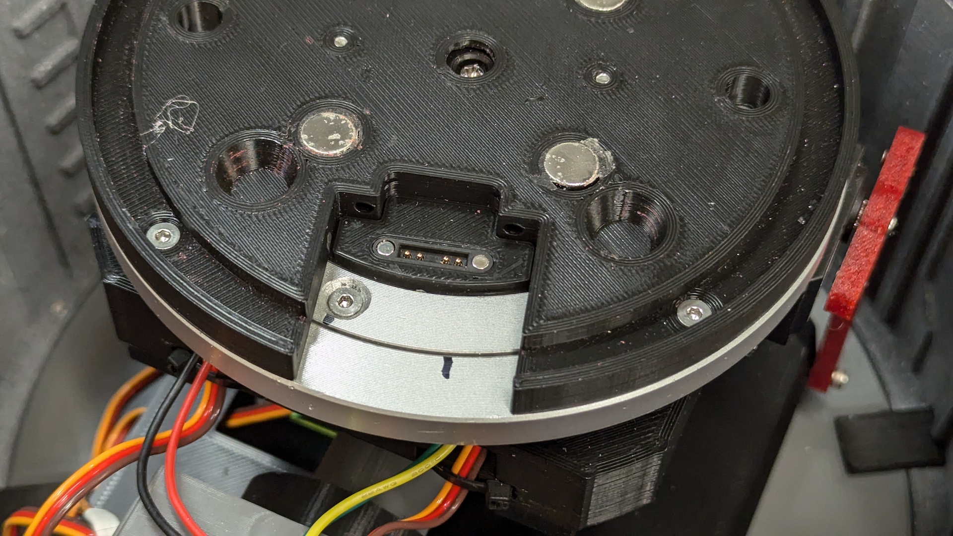
The wiring can be routed through the existing channels in the lift mechanism as needed.