
LowRider v4 CNC - KINEMATIC Tool-less Quick-Change Accessory Holder - supports laser, drag knife, pen, etc (v5.0)
Obliczymy ostateczną cenę na podstawie wybranego pliku. Sprawdzisz ją i zaakceptujesz przed płatnością.
Zapisane na tym urządzeniu.

LowRider v4 CNC - KINEMATIC Tool-less Quick-Change Accessory Holder - supports laser, drag knife, pen, etc (v5.0)
- Ocena
- 4,667 / 5
- Polubienia
- 63
- Pobrania
- 377
- Wydruki
- 1
- Wyświetlenia
- 2927
- Oceny
- 3
Aktualizacja u źródła:
Informacje o modelu
- Źródło
- Printables
- Kategoria
- Tools
- Licencja
- Creative Commons — Attribution — Noncommercial — Share Alike
This allows use of my earlier kinematic accessory tool mount on the awesome new LowRider v4 CNC.
Here's an old-yet-helpful video I made about the earlier version (which was for LowRider v3):
This whole deal is an adaptation of a Maxwell Kinematic coupling. You can read about that here: https://en.wikipedia.org/wiki/Kinematic_coupling#Maxwell_coupling
Original motivation was a nudge from Jamie K on the V1 Engineering forum.
Speaking of which, Jamie has now remixed this in a way that requires no acorn nuts, no screws for troughs, only one magnet on one side, no need for drilling any magnets for additional countersinking, and no need for prying any magnets out for flipping them. Check out his remix here. His remix avoids acorn nuts and avoids troughs made from screws, all by having both “mounds” and “valleys” made from 3D printed plastic. Here's a photo of Jamie's remix:

What's new?
The previous version was designed for LowRider v3. This new “Main Mount” enables use on LR4. Since the only part that needed modified was the “Part A, Main Mount,” only the new version of that part is provided here. For the other parts, you can download and use those from either…
… Jamie's excellent remix that requires less hardware:
…or my earlier listing:
Also, this is backwards compatible, so if you already made a set for your LR3, you can use all of it on an LR4 except the old main mount.
Caveat:
- Depending on the size and shape of whatever tool you attach, you should double check your range of X axis travel, as your tool's shape may result in a reduction of X axis travel, in order to avoid a collision at the X max side.
Notes:
- The XY offset of the tool from the router bit center is affected by both whichever tool holder you attach and the radius of what tool you add to your tool holder. If you really need to coordinate both the router bit center and the attached tool center, then for any estimated XY offset shown below, remember to measure and verify before you do any actual drawing or cutting. This other listing of mine can probably help with that.
- Estimated XY Offset — when using Jamie's fixed based and mobile base (link) — and before adding any specific tool holder:
X = 72.43 mm
Y = 20.79 mm - Estimated XY Offset — when using Jamie's fixed based and mobile base (link) — and this pen holder and a typical Sharpie marker (includes radius of the marker):
X = 84.72 mm
Y = 20.79 mm
- Estimated XY Offset — when using Jamie's fixed based and mobile base (link) — and before adding any specific tool holder:
- Two versions this new “Main Mount” are now offered here in this listing:
- On one, I designed a narrow slot that is intended to allow a Tiny Touch Plate (from Ryan's store) to be stored in the holder clip that he designed on the upper tool mount. If this prints well, and works, great. If not, then my own touch plate (which is wider than Ryan's) does indeed store well in the upper mount clip, as it then “leans” its edge against the lower tool mount, out in front of it.
- That said, a version without that slot is also offered, and is probably easier to print. This second version is courtesy of fellow V1 maker Aza ( @AzaB2C — on V1 forum here). Kudos and thanks, Aza! (As of April 14, 2025, I tweaked his model to clean up some stray geometry left over from removing the slot.)
- I changed the previous targeted angle of the mounted “Fixed Base” part from this:

… to this new angle for LR4:

…which, when attached to the main mount, looks something like this:

…where the LR4 core would be just to the right of this side view. The reason for this change was to minimize the offset distance away from the gantry, in order to help strengthen the mount's rigidity.
Speaking of which, this mount does seem more rigid than the previous version, owing in part (I think) to the fact that it's attached at three points instead of two in the previous version. The three points of attachment to the existing LR4 core's tool mounts are revealed in the simple directions for…
Assembly and Installation
- Print all parts and install all magnets / washers as desired. See links below.
- Using M3 x 16mm screws and M3 nuts, attach your desired tool holder(s) to one or more “Mobile Base” part(s). There are capture slots for the nuts.
- Using M3 x 16mm screws and M3 nuts, attach the “Fixed Base” part to the “Main Mount.” There are capture slots for the nuts.
- To install the combined assembly of Fixed Base and Main Mount to the LR4 core:
- On the top and bottom tool mounts, on the right side of each, remove the two M5 x 30 mm screws,
- Place the “Main Mount” part in position. (Mine snapped in with an audible click.)
- Replace the two original screws with M5 x 45 mm screws. (That makes two of the three points of attachment.)
- Install an M5 x 30 mm screw vertically down through the spare auxiliary mount hole on right side of the bottom tool mount. Use an M5 nut on the underside. There is no capture slot for this. (That makes the third point of attachment.)
- Magnetically click a “Mobile Base” toolholder onto the “Fixed Base.”
- Done!
Hardware / BOM:
- Filament of your choice (I'm using PLA)
- These disk magnets: note:
- The original Amazon listing I had linked seems to have been taken down, so I sourced a new current listing (see link below) that seems to be the same magnets. The disk magnets are about 32 mm in diameter and about 6.86 mm thick. New listing: https://amzn.to/46Z643n
- Two M5 x 45 mm screws (from my stash but like these): https://amzn.to/3Wgltqa
- 12 or more M3 x 16mm screws & nuts from this assortment: https://amzn.to/3OoX53Y
- Some washers that are about 1.25" in diameter. Be sure to get steel washers that are subject to magnetic attraction. (Not all are! I think if it says “galvanized” then it is.)
If you are using my earlier design parts that require more hardware,
- Two M4 x 10mm / 12mm screws & nuts from this assortment: https://amzn.to/43c0wie
- Three (3) of these ¼"-20 acorn nuts: https://www.lowes.com/pd/Hillman-3-Count-1-4-in-Nickel-Standard-SAE-Cap-Nuts/3035978 (Or if you want to have a stash: https://amzn.to/42Rtfcu - but see the note on earlier Printables listing about the differences between brands. The Amazon listing is the one that is about 2.7mm taller than the Hillman brand from Lowe's.)
COMPATIBLE TOOL HOLDERS:
- Air Mist Mixer Mount: https://www.printables.com/model/560988-lowrider-3-cnc-add-on-kinematic-air-mist-mount-for
- Pen Holder Inverted, remix of Jamie's inverted pen holder: https://www.printables.com/model/484869-lowrider-3-cnc-add-on-kinematic-pen-holder-drag-kn
- Laser mount for NEJE A40640 Diode Laser: https://www.printables.com/model/485419-lowrider-3-cnc-add-on-kinematic-laser-mount-v40-de
- Pen Holder, not inverted, v4.0 - generic design for pens on LR3 Dust Shoe, made for this v4.0 kinematic system: https://www.printables.com/model/489020-lowrider-3-cnc-add-on-kinematic-pen-holder-v40-gen
- Drag Knife Holder v4.0 - 1.0mm spring leaf (for drag knife such as sold by V1 Engineering): https://www.printables.com/model/489040-lowrider-3-cnc-add-on-kinematic-drag-knife-holder-
Printing tips
- Print as oriented.
- Suggested layer height with a 0.4mm nozzle: 0.28mm — I tried printing with a thinner layer height, but then the bridging (over the slot for the Tiny Touch Plate) did not do as well.
- Supports are encouraged. I regret this, but because of the slot intended to accommodate the Tiny Touch Plate, the design is complicated just enough that supports seem called for. I switched on Tree Supports, checked the preview, and added some support blockers to reign in the madness. See pics below. The one support blocker shown in the lower left forced bridging over the slot, as opposed to having a tiny slot full of support material.


A full “clock face” of nut capture slots on back:

Backwards compatible - my old parts shown attached here:


Change log:
- April 14, 2025 3:00am — I added both a STEP file and a Fusion 360 archive file, to the included version that has no slot for a Tiny Touchplate. This was as requested by fellow maker @GreenLightDesignCo.
- April 14, 2025 3:00am — I tweaked the included version that has no slot for a Tiny Touchplate, which is probably easier to print, and was originally courtesy of fellow V1 maker Aza ( @AzaB2C — on V1 forum here). Kudos and thanks, Aza! I tweaked his model to clean up some stray geometry left over from removing the slot.
- April 14, 2025 3:00am — I added info to the Notes area of the Description, regarding XY offset of the attached tool from the router bit center. See above that new info.
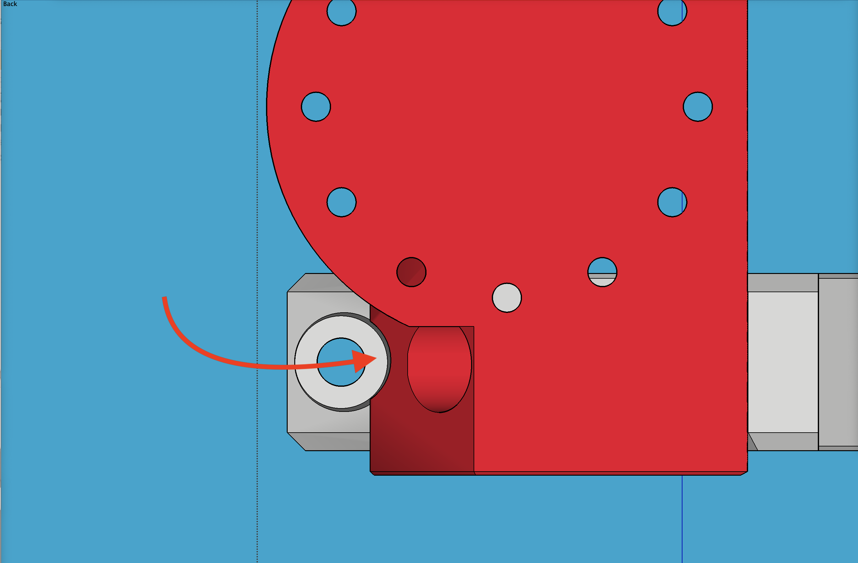
- October 24, 2024, ~8:30pm — Re-uploaded because a tool access notch was on the wrong face. Corrected it. The notch allows screw to be inserted in the lower tool mount's tensioner adjustment screw hole. The corrected notch is shown here:
- October 24, 2024, ~5:00pm — initial release posted. Consider this as “in beta.”
My PayPal tip jar: https://paypal.me/design8studio
Various LowRider 3 CNC remixes:
View all my models and remixes on Printables:
*Amazon product links are affiliate links.
Keywords: lowrider 4