Travel Telescope
Obliczymy ostateczną cenę na podstawie wybranego pliku. Sprawdzisz ją i zaakceptujesz przed płatnością.
Zapisane na tym urządzeniu.

An affordable, collapsible, Newtonian telescope designed for viewing the inner solar system - especially the moon.
- Ocena
- 0 / 5
- Polubienia
- 11
- Pobrania
- 51
- Wydruki
- 0
- Wyświetlenia
- 729
- Oceny
- 0
Aktualizacja u źródła:
Informacje o modelu
- Źródło
- Printables
- Kategoria
- Physics & Astronomy
- Licencja
- Creative Commons — Attribution — Noncommercial
INTRODUCTION
I designed this Newtonian telescope after visiting Kitt Peak National Observatory. My goal was to take a detailed picture of the moon and have my device be easily transportable, so I could take it on a plane. An additional bonus was making it budget friendly.
ADDITIONAL HARDWARE
Below is a list of the additional hardware I purchased for this projected. Included are Amazon affiliate links (As an Amazon Associate I earn from qualifying purchases).
Aluminum Tent Poles: I used aluminum tent poles with an 8mm diameter for the support of this model.
Newtonian Reflector Telescope Mirrors: I bought this kit on Amazon with an objective and secondary mirror. The objective mirror is 144mm in diameter and has a focal length of 900mm. The secondary mirror is 25mm on its shortest side.
10mm Eyepiece: I used a 10mm eyepiece with a 1.25" fitting diameter.
Hardware: I bought an assortment of M3 screws, but primarily used ones with a length of 8mm and 10mm. Additionally, I used hex nuts for permanent parts and wingnuts for pieces that need to be adjusted. Springs are also required. Here is a list of all the hardware I purchased:
550 PC M3 Screw Kit: The 8mm and 10mm screws will get exhausted from building this project, but you will have a lot of hardware left over. I'm excited to have left over screws for future projects.
20 PC M3 Wing Nuts: 5 of the 20 wingnuts are used in this telescope. I was excited to have some extra wingnuts, but a print to convert some of the left over hex nuts of the 550 PC M3 kit could easily be modelled or found of Printables to save some money. (I will likely also model these in the future, and if you message me or comment that you'd like them I will jump on the project).
300 PC Compression Spring Kit: Once again I was excited to collect some extra hardware. If your on a tight budget, I suggest taking apart some pens to find the 5 springs you need for this telescope.
Tripod: The best practice for using a telescope includes the use of a tripod - I reused a camera tripod. A ¼-20 nut can be used with the “Tripod Mount” to attach the telescope to a tripod.
Feel free to comment or message me if you plan to order alternative parts and need any of these dimensions changed!
ASSEMBLY
With a total of 13 pieces this telescope takes some assembly. However the nice part is, that once assembled for the first time a majority can stay assembled during travel.
STEP 1: Assemble tent poles (or other 8mm diameter objects) that are at least a meter long.
STEP 2: Push the poles inside the slots on the “Objective Mirror Body”. Insert hex screws into the pockets of the “Objective Mirror Body”, and thread in 10mm M3 screws. Slide the remaining two main body parts and the “Spider Vanes” print onto the poles. It should be tiered as follows:
- (TOP) “Spider Vanes” Print
- “Eyepiece Body” Print
- “Central Body” Print
- (BOTTOM) "Objective Mirror Body" Print
(The exact position of the “Eyepiece Body” and “Central Body" doesn't matter right now, just give yourself space to work). Insert hex screws into the pockets of the remaining body pieces, and thread in 8mm or 10mm M3 screws.


STEP 3: Push four 30mm M3 screws through the holes “Objective Mirror Shell”, and fasten one 30mm M3 screw through the center of the “Secondary Mirror Shell” with a hex nut. (Push means no nut yet, fasten means with nut).
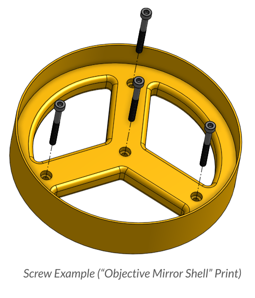

STEP 4: Fit the mirrors! Push the objective mirror into the “Objective Mirror Shell”; (I wear latex gloves to prevent smudges). The objective mirror should not be able to move! if it feels like it will fall out, use some tape around the inside diameter of the print. For the secondary mirror use tape or glue to firmly attach the secondary mirror to the “Secondary Mirror Shell”.
STEP 5: Put springs on the screws of the objective mirror assembly and push the insert the screws through the holes on "Objective Mirror Body" Print. Use wing nuts to fasten the assembly until you feel light resistance from the springs. Fasten three 12mm M3 screws through the holes on the spider vanes, and tighten with hex nuts. Put a spring on the secondary mirror assembly, and insert the screw into the center hole on the spider vanes. Tighten with a wingnut.


STEP 6: Using a single 10mm M3 screw and a single hex nut fasten the “Focuser Case” to the "Eyepiece Body". Thread the “Eyepiece Focuser” onto the “Focuser Case”.
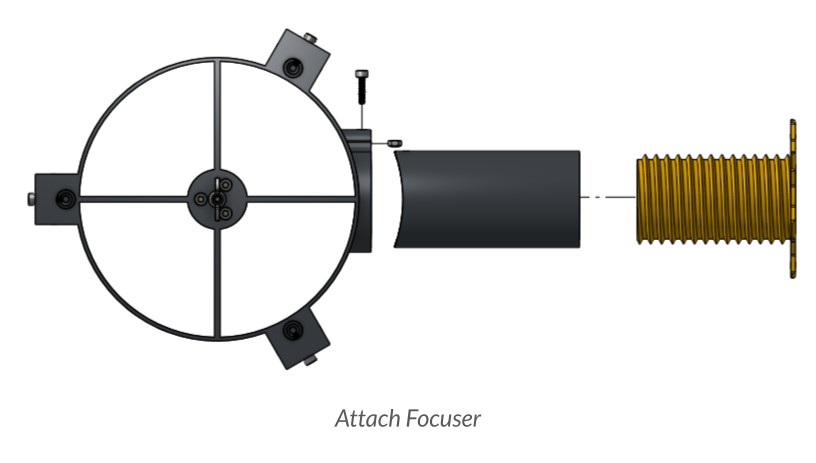
STEP 7: Begin Collimation!
COLLIMATION
The goal of collimation is to align all the mirrors and lenses. You'll know you have successfully collimated your telescope, when you can see a focused image.

Successful

Not Successful
Lets begin with understanding what we are trying to do. The focal length is the distance where all light is reflected back to a single point. For this telescope, that is 900mm (if you use the mirrors listed in the “additional hardware” section). Usually, all 900mm is travelled linearly, but we use a secondary mirror to alter the path 90 degrees. This is important: the secondary mirror doesn't change the focal length, it simply changes the direction of the light! Next, we find the focal length of the eyepiece; (eyepieces generally list this distance). For our example the eyepiece focal length is 10mm. We do some simple math and add the focal length (900mm) and the eyepiece focal length (10mm) to get 910mm. This is the total distance light should travel from the objective mirror to the eyepiece.

How do we actually do this?
STEP 1: Insert the pinhole cover into the eyepiece focuser to guarantee you are looking down the center.
STEP 2: Look through the pinhole at the secondary mirror. Slide the eyepiece assembly up and down the support beams until you barely see only the shell of the objective mirror. Adjust the screws on the eyepiece assembly as needed to keep the objective mirror centered on the secondary mirror.

Additional note: Once I have the eyepiece assembly fastened, I like to move the “Central Body” print toward the “Objective Mirror Body”, so the weight is more balanced on the "Central Body" print.
STEP 3: Continue to look through the pinhole, but this time focus on aligning the “Spider Vanes”, so they are centered. To do this use the wingnuts on the bottom of the telescope.


STEP 4: Let the telescope acclimate outside, and point it at a far away object (NOT THE SUN). Insert eyepiece and rotate focuser until your object becomes clear. Congratulations your telescope is collimated!
If the object is not becoming focused here are a few troubleshooting methods:
- Wait: Your telescope really does need time to adjust to the outside temperature, so it could simply still be in that process.
- Choose a different object: The object does not have to be the moon. You can select a far away street sign or a tree.
- Adjust the eyepiece assembly along the beams: If you use an alternative eyepiece, it is possible the correct focal length no longer falls with-in the range that the focuser can be adjusted to. To solve this, rotate the focuser and try to tell which way the eyepiece needs to move, and slide the whole eyepiece assembly up and down the telescope in the corresponding direction.
I will continue to update this list, as needed. Feel free to reach out in the comments or message if you reach an obstacle.
TELESCOPE BASICS
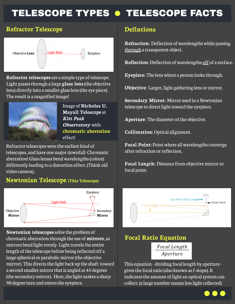
If you're interested in learning more about the basics of telescopes - specifically refractor and reflector telescopes - here is an infographic I made for the basic concepts and terminology that I discovered while making this model.