
A different type of 3D Maze
Obliczymy ostateczną cenę na podstawie wybranego pliku. Sprawdzisz ją i zaakceptujesz przed płatnością.
Zapisane na tym urządzeniu.

This is a 3D "van Deventer maze" Find the right path by making movements in the 3 projection planes. It not so easy
- Ocena
- 5 / 5
- Polubienia
- 8
- Pobrania
- 20
- Wydruki
- 1
- Wyświetlenia
- 192
- Oceny
- 1
Aktualizacja u źródła:
Informacje o modelu
- Źródło
- Printables
- Kategoria
- Puzzles & Brain-teasers
- Licencja
- Creative Commons — Attribution — Noncommercial — Share Alike
This design of a 3D Maze is originally based on an article from Scientific American from September 1988. There this is called “a van Deventer Maze”, or “Oskar's Cube”.
You can also find more info about Oskar van Deventer and his puzzles here:
https://oskarvandeventer.nl/bitsandpieces.html
https://www.oskarvandeventer.nl
In my version of the maze I made the “cross” in a slider mechanism. This makes the total more compact.
The object is to move the "actuators" from one corner, indicated with a circle, to the other, indicated with a square and back.
You have to figure out that a possible movement in one dimension can be blocked in another dimension.
Citation out of the article from Scientific American:
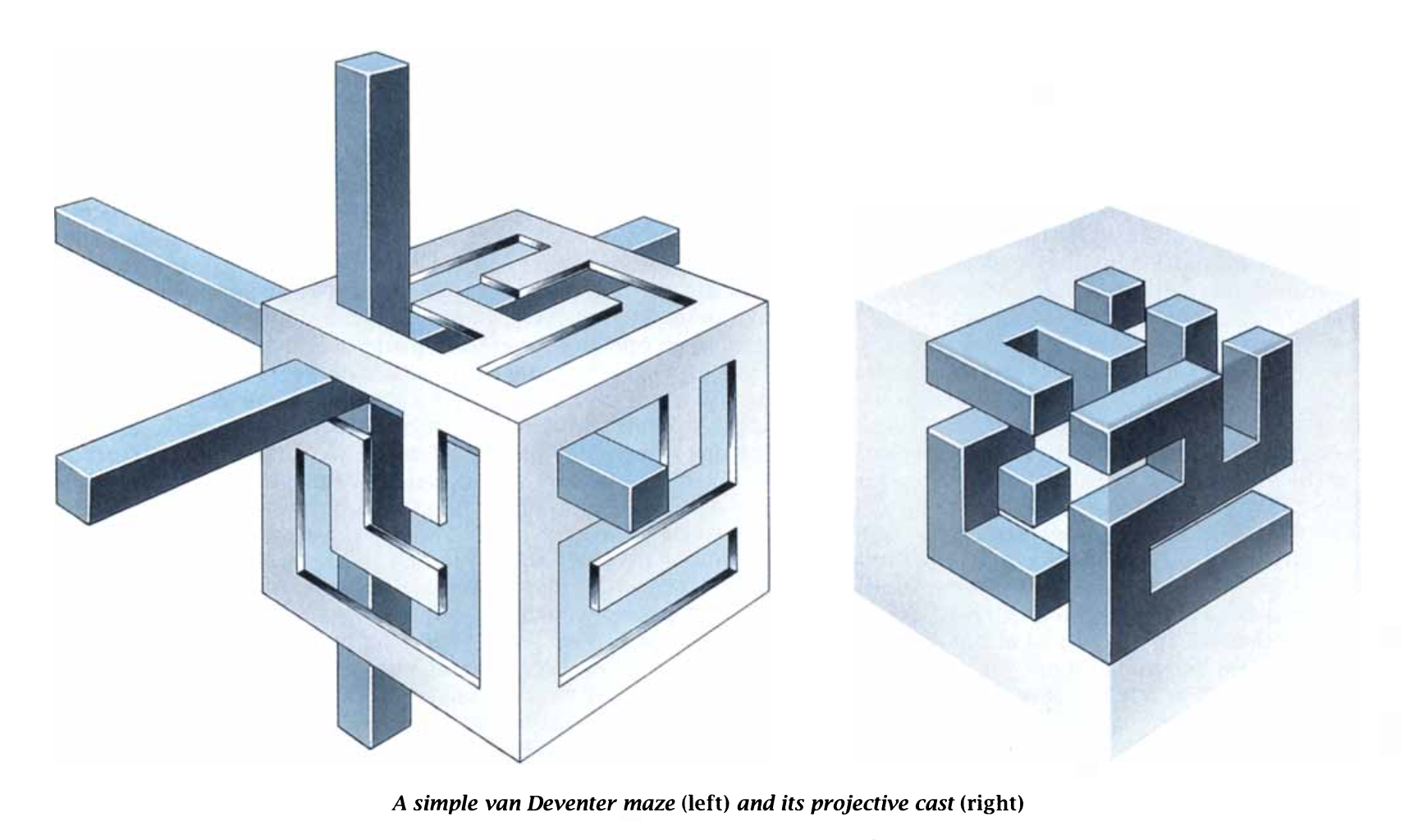
The secret lies in the sides of the box. They are two-dimensional “control mazes” wood surfaces in which slots have been cut. A cursor consisting of three mutually perpendicular wood spars registers one's position in the hollow maze. Each spar passes from one side of the box to the other, sliding along the slots of the control maze on each side. Not surprisingly, the two control mazes on opposite sides of the box are identical. In this way van Deventer can produce a single three-dimensional maze from three pairs of two-dimensional mazes.
In the simple example shown above one starts with the cursor in one corner of the box and tries to manipulate it into the opposite corner. Each spar is pushed into and pulled out of the box, automatically moving the other two spars (if possible) along slots in their respective control mazes. It might seem that to solve a hollow maze one merely solves each of the three control mazes. But this is not so. Although each of the control mazes can be easily solved, the hollow maze is quite difficult.
The difficulty lies in the fact that possible moves on one control maze may be blocked by another control maze. Moreover, it is not clear in which order the cursor's three spars should be pushed or pulled. There may be several possible moves at any given position of the cursor. To solve.
Note: I transformed the simple spars into sliders/actuators. That makes the total less bulky and the sliding motion better.
My design history
The first modesl I published several years ago:
https://www.printables.com/model/46551-3d-maze and
https://www.printables.com/model/46552-mini-maze
it was designed/programmed with OpenScad.
It was based on an 8X8X8 grid.
This time I redesigned the model completely with Fusion 360 and an 10X10X10 grid. This will likely make it a bit more challenging.
To design the path for this type of maze you have to create the path(s) so that in the projections on the walls there will be no “islands”.
I designed the “solution path” first, then added some “error paths”. After that I constructed the box around it and projected the paths on the walls.
Overall I tried to make the design a bit more pleasing, sturdier and better to print.
It is best to operate the mechanism with both hands.
Instructions
To build the model you have to print out each wall (panel). I did this with the outside on the build plate (Satin) to have a nice outside surface and a stronger structure due to the print orientation.
You need to print 2 full actuators. The third one is split. First assemble all the actuators as is shown in the pictures (without knobs) and then glue the two parts of the third actuator together.
To guide you I added everywhere little holes where you can press in very small pieces of filament to align the parts. Maybe you have to ream the small holes a bit with a 1.8 mm drill.
Don't forget to add the rings to the actuators, they are important for smooth operation.
You have to print the knob and the ring 6 times. Test if the knobs can be easily be screwed on to the actuators. If not polish the threads on the actuators a bit. Actually you can re-cut the threads, but it is an ISO 9 mm thread and therefor not so common. The knobs are the very last thing to mount.
Final assembly is a bit tricky. Glue the panels together in one three wall part. Make sure that all is correctly oriented. Each corner has a number on the inside ( 1 - 8 ) make sure that in a 3D corner all the numbers are the same . Start with number 1. To glue the parts use the little holes to put in very small pieces of filaments, max 5 mm length. When these pieces are too long you will have problem to assemble the total. The holes are also only 3 mm deep. I used several types of corner clamps. You can buy them or print your own. You can find several corner clamps here in Printables.
I used UHU “Allplast” for gluing. The bond is not really strong, but you have a few minutes to put the parts together correctly. Then let it cure for at least an hour. Further you can remove some glue stains with acetone (as long as you don't use ABS material).
Insert the actuator/slider structure after you have glued the first 3 panels together. Be sure to insert the actuators/slider in a position that is on a path. It is possible to put them in a “non reachable” position. Then you will never find the solution. I recommend to move the actuators as soon as you have inserted them in the start (Nr 1) or end position.
Then orient the other 3 panels and glue all panels, one by one.
The order of assembly is shown below.
Check if everything runs smoothly. Without knobs the movement can be a bit difficult because of cogging.
In the end screw the knobs on the actuators in such way that a smooth movement is possible. Adjust the knobs. Try out before you apply glue. Then put them on with some glue, I used UHU ""Por". Then you still will be able to reposition the knobs later. The knobs and the inside rings provide a smooth operation and prevent cogging as much as possible. Still you likely have to operate the sliders with both hands.


I wish you a lot of fun with this brain teaser.
As always:
- When you like the design, give me a few likes.
- When you print it, share a picture.
- When you have questions, just ask.
PS: In the last picture you see the evolution from my first design:
year 2016, OpenScad, printed on an XYZ-Mini.
And this one:
year 2025, Prusa MKS4S, Fusion 360.
PPSS: Of course you can simplify by going back and replace the slider mechanism by a 3D Cross. Like in https://www.printables.com/model/46552-mini-maze and https://www.thingiverse.com/thing:2844519