
RoeTest Nixie Adapter
Obliczymy ostateczną cenę na podstawie wybranego pliku. Sprawdzisz ją i zaakceptujesz przed płatnością.
Zapisane na tym urządzeniu.
Design related to Helmut Weigl's RoeTest tube tester: My approach for a versatile Nixie tube adapter
- Ocena
- 0 / 5
- Polubienia
- 1
- Pobrania
- 20
- Wydruki
- 0
- Wyświetlenia
- 111
- Oceny
- 0
Aktualizacja u źródła:
Informacje o modelu
- Źródło
- Printables
- Kategoria
- Electronics
- Licencja
- Creative Commons — Attribution — Noncommercial — Share Alike
General information
At the end of 2024, I set up version 11 of Helmut Weigl's RoeTest. In the process, I created some 3D designs that I am making available to the community in this collection. You can read more information about my build of the RoeTest and the use of the designs published here in my build report at Radio-Bastler.de (German) or on the RoeTest website (German).
About this Design
The RoeTest tube tester can be used to test Nixie tubes (non-biquinary) and Inditrons by using a Nixie adapter:
My design for a Nixie adapter is very compact and uses D-SUB-25 connectors, so Nixie socket boxes can be built just as easyly as ordinatry RoeTest socket boxes. The main difference is the connector that is very cheap and allows easy wiring for up to 17 cathodes.
Also my Nixie adapter has build in resistors with values to covering the complete spectrum of Nixies out there. Anode channel seclect switches allow to connect the anode to up to two anode pins. So the Nixie adapter is easy to use and very versatile. Also very safe to use, since all components are inside the adapter.
However: I am not sure if anybody is able to reporoduce it! I have uploaded all the files, so it should be possible. But you will have to build the PCBs (Kicad project included!), get all the parts etc. In case you give it a try: Good luck and let me know ihow it turned out or where you gave up!
There are four different boards:
The anode channel select board just contains two rotary switches and JST-XH-connectors for wiring:

The anode resistor board contains a rotary switch to select the anode resistor:

I opted for power resistors up to 5W. This might be a bit overkill, but so there is no need to worry if there are short circuits.
The relais board contains four relais for multiplexing the socket pins. It also contains JST-XH connectors to collect all the wires from the two anode selector boards and connects them to the output connector board:

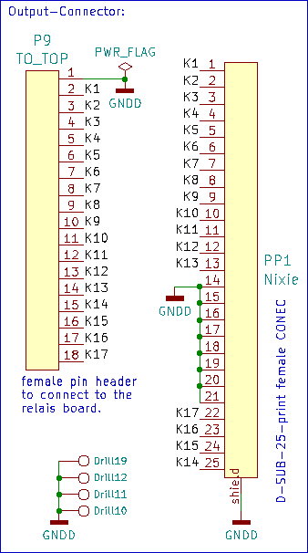
The output connector board just connects the outputs to a D-SUB-25 female connector:
Print all printed parts in PETG in variable layer height 0.1…0.3mm. You will need some M3 screws and both 12mm and 15mm distance bolts to stack the boards. Make sure to add washers where the screws might cause a short circuit!
Compensating for part shrinkage
For a perfect fit I recommend to compensate for material shrinkage: Print a sample using the same material and settings and measure shrinkage of the printed parts compared to the model. Then in the slicer apply a size scale factor in x- and y- direction. In my designs I usually have to use a factor of around 1.0025…1.0045 to compensate for my PETG material.
Happy printing!
If you like this design, then please leave a like and also post a make in the comments.
You might also want to check out my other designs