
Magnetic Conic Sections(Adjustable Magnet Sizes, Designed for 12.65mmX5.05mm)
Obliczymy ostateczną cenę na podstawie wybranego pliku. Sprawdzisz ją i zaakceptujesz przed płatnością.
Zapisane na tym urządzeniu.

A 3d conic sections model that displays a parabola, ellipse, and circle while using magnets to streamline usability.
- Ocena
- 0 / 5
- Polubienia
- 2
- Pobrania
- 15
- Wydruki
- 0
- Wyświetlenia
- 127
- Oceny
- 0
Aktualizacja u źródła:
Informacje o modelu
- Źródło
- Printables
- Kategoria
- Math
- Licencja
- Creative Commons — Attribution — Noncommercial
Mission:
I was given the task of designing a solution for a math teacher who had requested a model of the conic sections to help her students deepen their understanding of the topics they were learning about. I included 3 conic sections in my model, the circle:


, the ellipse:


, and the parabola:


Printing notes:
I used a K1 Max and a Prusa MK3S to print my models. These printers are known for their reliability so my tolerances are pretty low. I have attached a Solidworks file of the entire thing in case anyone wants to adjust the print for different magnets. Keep in mind that the Solidworks file is not meant to be directly printed; instead, it is. meant to be modified and then printed. Note that Solidworks files(.sldprt) are also compatible with Onshape.
Assembly Instructions:
For reference, I have labeled the different models that you will need to assemble.


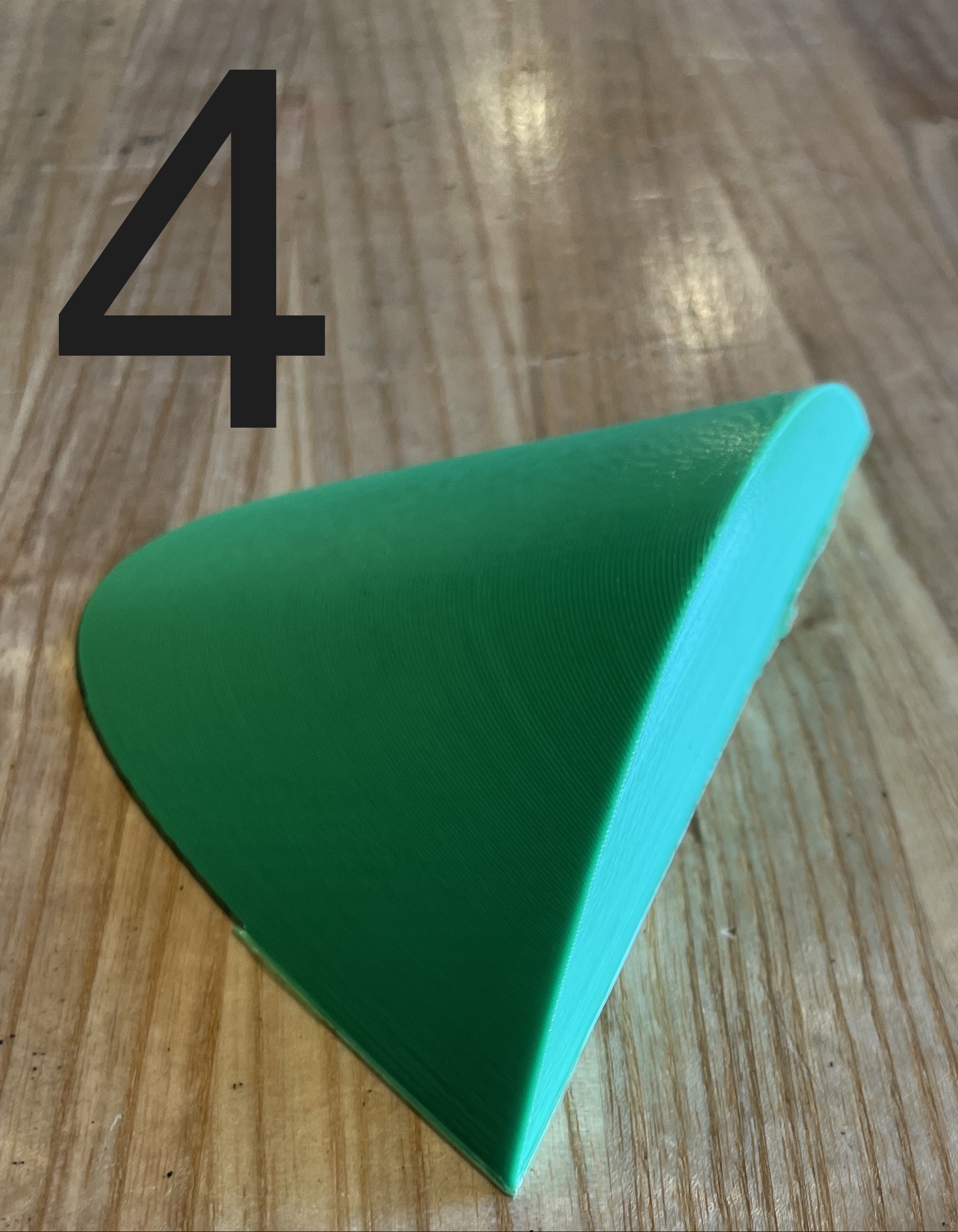
Inserting Magnets:
The magnets fit pretty well especially if you use a mallet or force to get a really good friction fit. Not all of my magnets were exactly the same size so I had to use some super glue to ensure a tight and uniform fit.
Step 1:
Insert the magnets into model 1 and the circle on the model 2, faces shown below:
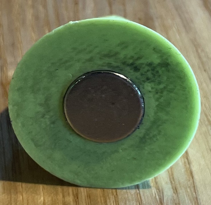

Step 2:
Insert the magnets into the ellipse on model 2 and the ellipse on the top of model 3, faces shown below:

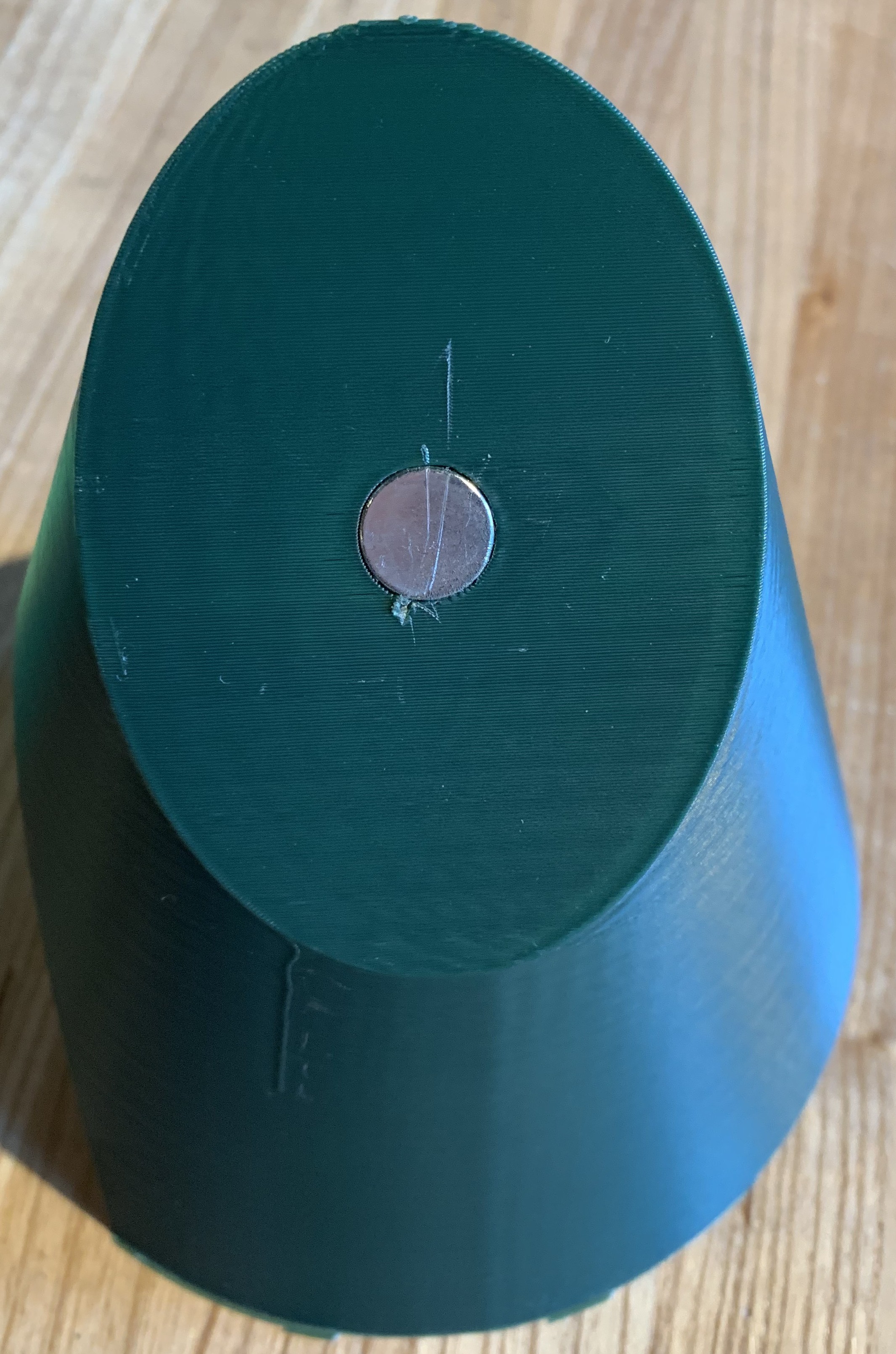
Step 3:
Insert the magnets into the parabola on model 4 and the parabola on the side of model 3, faces shown below:


Design Choices and Setbacks:
Colors:
I wanted each shape to be distinct, so I chose different colors for each part. I didn't want it to be an eyesore so I chose to go with a color gradient. I had a lot of green filament lying around so I decided to do a green gradient but as the maker, it is your choice what color you pick.

Connection Method:
There were multiple options for connection methods, such as pegs or Velcro, but I ultimately decided to use magnets due to their durability and usability. Magnets have a strong fit and a clean sound compared to the headaches that come with Velcro falling off and pegs snapping.
Magnet Size:
I originally started with a smaller magnet size but I found it to be too weak for the scale of the project that I was doing so I switched to larger magnets.

Printer Troubles:
When I first started this project I attempted to print it on a modified CR-10. This CR-10 has a 1.0mm nozzle instead of a standard 0.4mm nozzle to make it more filament-efficient. My CR-10 is a little old and is not in tip-top shape anymore due to this I had to do a lot of fine-tuning to fit the magnets. Even after this every time I printed the friction fit I would get different results leading to some of the fits being stronger than the other. THis issue ultimately let me to give up trying to print on the CR-10 and to use my K1 max and my Prusa MK3S to get the job done.
Failed parts:

Magnet tests:
As I mention I had to do a lot of testing to try and find a set of dimensions that fit my magnets. In the picture below the tests range from biggest to smallest dimensions(left to right). The 2 tests to the left are printed at a 45 degree angle because that is the angle that the circle on the Ellipse Midsection prints at is 45 degrees. Ultimately I didn't use any of the dimensions that I tested here because I switched magnets and printers.
