
Double Coupler HeadPhone (test) Fixture (DCHPF) - KB501X & IEC 711 mount
Obliczymy ostateczną cenę na podstawie wybranego pliku. Sprawdzisz ją i zaakceptujesz przed płatnością.
Zapisane na tym urządzeniu.

Headphone measurement rig for Left and Right channel, variable headsize
- Ocena
- 5 / 5
- Polubienia
- 18
- Pobrania
- 101
- Wydruki
- 3
- Wyświetlenia
- 1060
- Oceny
- 1
Aktualizacja u źródła:
Informacje o modelu
- Źródło
- Printables
- Kategoria
- Audio
- Licencja
- Creative Commons — Public Domain
Inspired by the GRAS 45CC
Compared to my old KB501X plate the DCHPF enables proper fitment of the headphone and the ability to measure left and right channel more seamlessly. Significantly more rigid structure, fully secured coupler and ear with clamping hub.
The headsize can be adjusted to simulate earpad compression that is closer to a specific individual. The standard width value of 14.5 cm with the 7.5 mm spacer is equivalent to the GRAS 45CA.
When aligning the witness marks on the headband bracket with the nuts, DCHPF will have similar Ear-Entrance-Point (EEP) to vertex distance as the maximum outlined in the ITU-T P.58 recommendation.
Changelog
2025-09-22:
- New Coupler Clamp V2
Thanks to contribution from User BARON KOKOS a new coupler clamp is available that enables changing the coupler more quickly and without tools. This new clamp is recommended because it simplifies assembly and usage. - Added compatibility note for couplers
- Updated assembly instructions, drawings and pictures to accommodate the new coupler clamp
2025-04-19:
- New earplates (earplate V3) with thicker bottom wall, thighter diameter for the silicone ear opening and adjusted holes for the heatset inserts
- New Headband Bracket (V2) with extended side region to provide better fit with headphones that have two contact zones on the sides of the head (Audio Technica wings, HD 650); adjusted the slots to reflect the actual limits of adjustment
- New High-Clearance Stand: Only increases total height by 25 mm but enables clearance for any headphone termination
Bill of Materials
| Part Nr. | Qty. | Part Name | Description |
| 1 | 1 | Pin Arc | 3D-Printed |
| 2 | 2 | Coupler Clamp V2 | 3D-Printed optional MIRROR |
| 3 | 2 | Spacer for 145mm width | 3D-Printed |
| 4 | 1 | Earplate L V3 | 3D-Printed MIRROR |
| 5 | 1 | Earplate R V3 | 3D-Printed |
| 6 | 1 | High-Clearance Stand | 3D-Printed |
| 7 | 1 | Headband Bracket V2 | 3D-Printed |
| 8 | 10 | Bambu Brass Insert M4 x 6 x 6 | SKU: AB016 |
| 9 | 4 | Bambu Anti-Vibration-Feet | SKU: FAZ004-N |
| 10 | 6 | DIN 7979 - Ø12 x L50 - M6 | Pull-Out Dowel Pin |
| 11 | 22 | ISO 4032 - M4 - St | Hex Nut |
| 12 | 14 | ISO 4026 - M4 x 8 - St | Flat-Tip Set Screw |
| 13 | 18 | ISO 7380-1 - M4 x 10 - St | Button Head Hex Drive Screw |
| 14 | 6 | ISO 10642 - M6 x 16 - St | Hex Drive Flat Head Screw |
Additional: 60318-4 Coupler (make sure it is serialized) and silicone ears from Ali. The rectangular KB006X-style ear will not work.
The typical stick-microphone couplers with the 6mm electret will not work when both couplers are installed (see compatibility note).
For the headband-bracket I recommend using nut-sided M4 washers or flange nuts (EN 1661, DIN 6923 or similar).
Instead of ISO 7380-1 you can also use standard cylinder head screws (ISO 4762 M4 x 10).
Instead of the set screws you can also use the M4 x 10 screw (except for coupler clamp V2).
Coupler compatibilty note
The IEC 60318-4 based coupler cavity is usually the same. Available couplers differ in the microphone used (working standard microphones or non-standard (usually electret) microphone capsules).

The picture above shows the broadly available Type E610A Occluded-ear simulator cavity with a WS2P microphone capsule inserted (without protection grid). To the WS2P-Cartridge the preamplifier is attached.

Picture above shows the non standard electret microphone supplied with the typical “stick”-coupler. Its length is similar to the working standard package. The stick is a tube where a 6 mm diameter electret is glued at the end. The other end terminates into a BNC or similar connector.
Stick-style 60318-4 based couplers with total length exceeding 6 cm (including cable) cannot be used with both channels simultaneously in the standard 145 mm head-width setting of DCHPF.
The following coupler styles can be used with two couplers (left and right) installed at the same time:

From top to bottom:
- wide base for stand-alone insert earphone measurement
- modified E610A with short integrated non-standard ECM
- IEC 60318-4 based coupler with integrated microphone and preamp
The two lower couplers are ideal. The wide base coupler is problematic due to the cable exit which will interfere with the fixtures pin-arc:

Considering that the wide base coupler uses a spring-loaded interface a shim can be made to alter the orientation of the plug. The best fix is the use of small, right angle BNC-connectors on the cable connecting to the wide base.
Print Instructions
No supports.
For the earplate LR and the Pin Arc I recommend PET-G over PLA because it is more damped. Everything else can be printed with standard PLA. Wall loops and bottom/top-shell thickness should be adjusted in a way that the thin sections (ribs/thin walls) of the parts are printed solid.
Earplate should have a smooth contacting surface (feel free to experiment), I recommend Archimedean Chords (spiral) for the bottom surface pattern.
Pin Arc is prone to warping, I recommend a brim and adhesive.
Perform a fit-check of the pins, nuts and screws before assembly. Post-Process if needed.
Coupler Clamp V2 should be printed solid or with large wall thickness (>2 mm).
Assembly Instructions
Needed tools:
- 4 mm, 2.5 mm, 2 mm hex key/driver
Steps:
- Melt the M4 Brass inserts (8) into the earplates (4&5), has to be flush
- Screw the coupler into the Pinnae, when using a stand with integrated pre-amp, unscrew the stand part from the coupler
- Take the Coupler Clamp and slide the coupler into it
- Use the Pinnae Spacer to align the clamp with the silicone ear, the round bit goes into the ear:
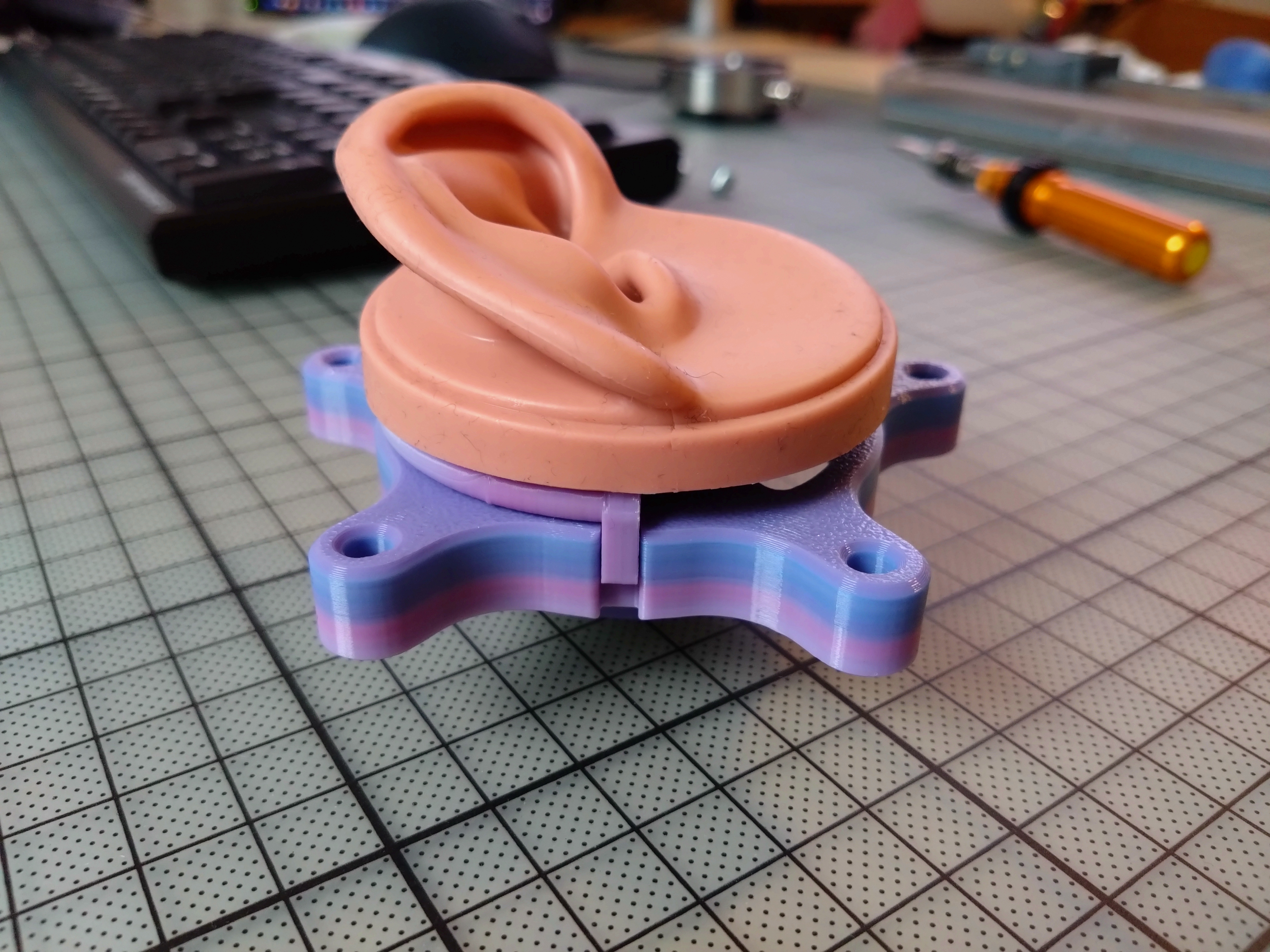
- Ensure that the Pinnae Spacer is not loose by pressing the clamp and the ear together
- Fixate the subassembly by using 2x screws (13) and nuts (11), recommended torque ~0.3 to 0.5 Nm
- Use the Pinnae Spacer to align the clamp with the silicone ear, the round bit goes into the ear:
- Take the subassembly and carefully slide the ear into the earplate, be sure not to pinch the lobe. Use the larger hex key to push the silicone into the socket if necessary.
- Screw it down using 5x screw (13)

- Screw it down using 5x screw (13)
- Install the Pull-Out Pins (3x 10) into the earplate using flat-head screw (14)
- Repeat steps 2,3,4,5 for the other channel
- Prepare the Pin Arc (1) by inserting all the hexnuts (11) and screwing in the set screws (12) (2 to 3 turns only)
- Assemble Stand (6) with Pin Arc (1) using screw and nut (13/11)
- Clip the spacer (3) onto the earplate's pin (optional)
- Slide the earplate assemblies into the Pin Arc until it is fully seated
- This may take some effort, it helps to loosen the flat head screws (14) so they can compensate for the tolerance, fully tighten them after assembly
- Once the earplate is fully seated, tighten the set screws
- Install the headband bracket (5) using Nuts/Screws (13/11)
- Push the Anti-Vibration-Feet (9) into the stand (6)
- Screw the pre-amps onto the couplers if necessary
When using Coupler Clamp V2 step 2 and 3 are replaced by
- push hex nut (11) into coupler clamp V2 (2)
- screw set screw (12) into the hex nut until you feel slight resistance from the flexible wall
- slide the pinna's hard socket into the clamp
- clamp's locating pin has to line up with the hole in the pinna's soft part
- fasten the set screw with low torque (0.5 Nm)

When in doubt, refer to the assembly step file.
For maintenance I recommend removing the flat head screws to slide the earplate assembly off with the pins still stuck inside the Pin Arc.