
Optical Runout Sensor for Micro Swiss Direct Drive (Ender 3/Pro)
Obliczymy ostateczną cenę na podstawie wybranego pliku. Sprawdzisz ją i zaakceptujesz przed płatnością.
Zapisane na tym urządzeniu.
I was looking around for a runout sensor since I upgraded my Ender 3 Pro with a Micro Swiss Direct Drive and found the…
- Ocena
- 0 / 5
- Polubienia
- 12
- Pobrania
- 77
- Wydruki
- 0
- Wyświetlenia
- 1310
- Oceny
- 0
Aktualizacja u źródła:
Informacje o modelu
- Źródło
- Printables
- Kategoria
- Creality Parts & Upgrades
- Licencja
- Creative Commons — Attribution
I was looking around for a runout sensor since I upgraded my Ender 3 Pro with a Micro Swiss Direct Drive and found the design by Sulfu, which is quite smart.
It utilizes an optical sensor and is compatible with transparent filament by implementing the reliable and simple shutter mechanism, which is magnetically levitated. Further it is rather small and lightweight. A fantastic design!
I remixed it and added a flexible square mount that snaps around the extruder stepper. Further, I adjusted a few tolerances and made some esthetical adjustments, so that it fits better my overall design.The small ball bearing is held in place by a 3mm printed shaft.
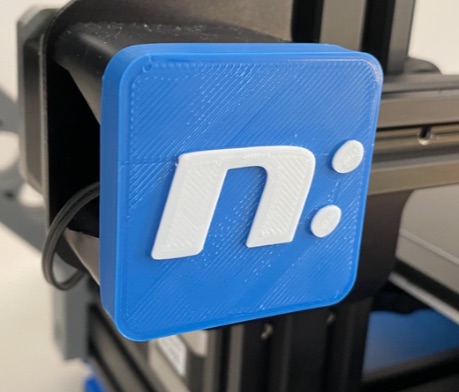
I put my personal logo on the front, but the stl I provide hasno logo in case you want it without or design something yourself.
Components:
1 x optical sensor
4 x magnets 3mm (diameter) x2mm
1 x ball bearing MR63
2 x screws M3 x 8mm
ca. 6cm PTFE tube 4mm in diameter
Print Settings
Printer Brand:
Creality
Printer:
Ender 3 Pro
Rafts:
Doesn't Matter
Supports:
Yes
Resolution:
0.12
Infill:
15-20%
Filament:
[
any PLA ](http://www.amazon.com/s?url=search-alias&field-keywords=any+PLA&tag=thingiverse09-20) any Post-Printing
Assembly, Wireing and Firmware Adjustments
Assembly
* Insert the ballbearing in the fork on the shutter and secure it with the shaft you printed.
- Insert the magnets in the holes on the shutter and in the housing. Make sure the magnetsrepell each other whenno filament is present. When the filament is inserted, the shutter will dip into the light barrier which signalsfilament is present. When no filament is present, the shutter will be repelled by the magnets and dip out of the light barrier, which meansno filament present.
- Insert the sensor into the housing.
- Insert the shutter and check that is can move smoothly in its gap and does not stick anywhere
- Re-check the if the magnets are inserted correctly (see above)
- Close the housing with the cover and the M3 screw
- insert some PTFE tube in the inlet and outlet of the housing (inlet ca. 20mm, outlet ca. 36mm) Wireing:
I have a SKR mini E3 v1.2 board to which the sensor is connected. As the sensor has three wires I use the PT-DET terminal on the board. Link to the board pining. The pinning on the mini E3 2.0 is identical for the PT-DET terminal.
Note
Pinning on the SensorGND | Signal | +5V
Pinning on PT DET:Signal(PC12) | GND | +5V
Make sure that GND and signal are crossed!
Firmware Adjustments:
At the time I write this the lates release of Marlin Firmware is 2.0.7.2 (but I use the latest bugfix 2.0.x anyways ). Make the following changes and recompile the firmware
InConfiguration.h enable (= remove the //):
define FILAMENT_RUNOUT_SENSOR
and
define FILAMENT_RUNOUT_SCRIPT "M600"
Inpins_BTT_SKR_MINI_E3_common.h make following changes (the file is located in the folder Marlin/src/pins/stm32f1):
Disable the PC15 connector and add the PC12 connector (which is on the PC-DET) as the sensor pin:
//
// Filament Runout Sensor
//
ifndef FIL_RUNOUT_PIN
//#define FIL_RUNOUT_PIN PC15 // E0-STOP
define FIL_RUNOUT_PIN PC12 // PT-DET
endif
- Disable Powerloss Detection completely by commenting the whole definition to avoid interferences. Usually the Powerloss Detection uses the PC12 connector, which is now the filament sensor pin.
//
// Power-loss Detection
//
//#ifndef POWER_LOSS_PIN
// #define POWER_LOSS_PIN PC12 // Power Loss Detection: PWR-DET
//#endif
If you like my stuff then please leave a 👍 and post a make. Thanks!