
Funny Frog Office Decoration
Obliczymy ostateczną cenę na podstawie wybranego pliku. Sprawdzisz ją i zaakceptujesz przed płatnością.
Zapisane na tym urządzeniu.
Love amphibians? Want one on your own desk? Look no further & get your own 13.8 cm x 7.0 cm x 8.3 cm funny frog stand!
- Ocena
- 0 / 5
- Polubienia
- 2
- Pobrania
- 5
- Wydruki
- 0
- Wyświetlenia
- 63
- Oceny
- 0
Aktualizacja u źródła:
Informacje o modelu
- Źródło
- Printables
- Kategoria
- Office
- Licencja
- Creative Commons — Attribution — Noncommercial
SUMMARY SECTION:
Love amphibians? Want to have one on your own desk? Look no further and get your own funny frog stand! With a compact 13.8 cm x 7.0 cm x 8.3 cm stand and a goofy, assemble-it-yourself frog engraving, this office decoration will take little space on your desk and always brighten your day. To create this build, I had assistance from classmates Cyrus and Ivan who created similar 2D art projects and helped me with issues I encountered. You can find Cyrus’s page here and Ivan’s page here. Thank you Cyrus and Ivan for making this project possible!
---------------
LESSON PLAN AND ACTIVITY:
I created this build as a final project for my high school Introduction to Engineering Design class. I aimed to use all the knowledge and tools I had gained about 3D printing throughout class to create any project that I wanted. Specific constraints for my 2D art decoration included:
- Should be no more than 1 cm in total thickness
- Should have a flat back
- Sketch must be started with a constraint box
- Dimensions should be detailed but efficient
- Should be able to fit inside a box no bigger than 225 cm2 in area
- All dimensions should be less than 25 cm
---------------
ASSEMBLY/CONSTRUCTION INSTRUCTIONS SECTION:
1. First, I started off with a rectangular sketch in the Front Plane and extruded that sketch by 0.5 cm. Then, I used the Appearances tool to project an image of the frog I wanted to create onto a face of that rectangular extrude, and used sketch tools (lines, arcs, circles, etc.) to trace that image onto a face of the rectangular sketch. The picture on the left below shows the specific options in the Appearances tool I used to project my image, and the picture in the middle shows the process of tracing the image. The last image is the final result for my sketch.

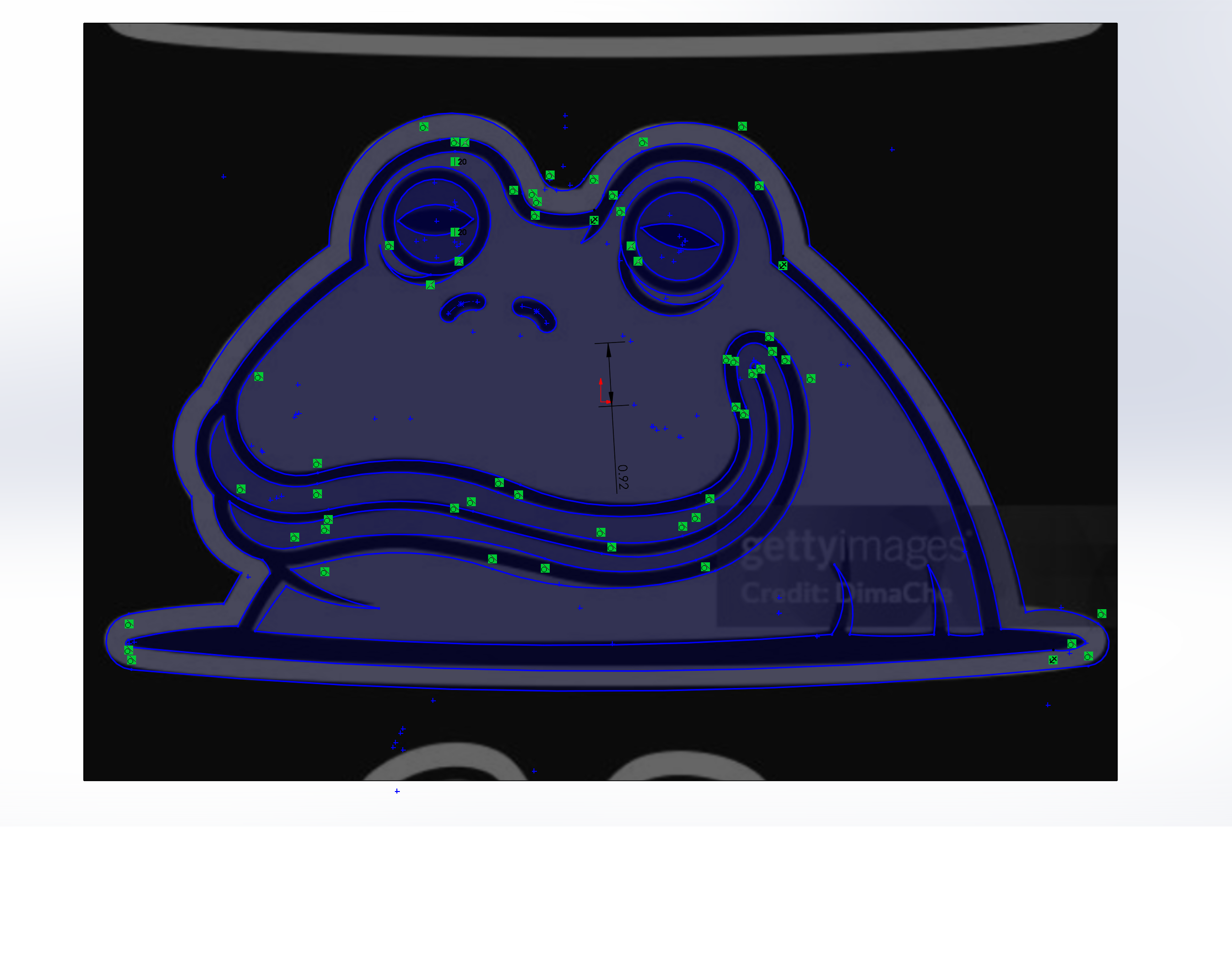

2. After tracing the frog, it was time to cut out each separate piece of the sketch to create the parts for my frog. Starting from the outer layer of the sketch, I used the Convert Entities tool to copy each set of lines into a new sketch, and then used the offset entities tool to offset the same lines by 0.02 cm (switching offset directions between inwards and outwards every time). This step is shown in the picture below.

3. Then, with all of the lines converted and offsetted, I used the Cut Extrude tool to create gaps between each layer of my sketch. After doing this for every single pair of lines in the drawing, I was able to create different parts that I could piece together for my build. The picture on the left below shows cuts I had to create to make each separate part. An example of a part that was created using cut extrudes is shown in the picture on the right.


4. After creating separate parts for each section of the frog, I used the Boss Extrude Tool to add a “dish” to the back of the frog. This dish would be where all the parts of the frog would fit during assembly. To create this Boss Extrude, I used the Convert Entities tool to convert the sketch of the outermost outline of the frog onto a new sketch, and then extruded that sketch towards the back of the frog extrude; however, I MADE SURE TO ONLY MERGE IT WITH THE OUTER LAYER.

5. Lastly, I used the sketch tool to create a sketch for a stand. I used the Revolve Tool to revolve the sketch 78°, with an horizontal axis of revolution under, but almost tangent to, the sketch. The process of the sketch being revolved is shown in the image below.

6. After printing out all the parts, your parts altogether should look like the parts in the picture below. Note that each set of parts are numbered 1-9.

First, take piece #4 (which is the outline of the frog), and fit it inside piece #9 (which is the “dish” where all of the parts will be). Then, take piece #3 (the lips of the frog), and fit it inside the corresponding engraving in piece #4. After, take piece #8 (the body of the frog) and place it inside the corresponding engraving in piece #4. Your frog build should now look like this:

Now, take pieces #5 (the grey eyelids of the frog), and place the bigger eyelid in the right hole of the frog and the smaller eyelid in the left hole. After this step, take pieces number #6 (the eyeballs of the frog), and place the bigger eyeball in the right hole and the smaller eyeball in the left hole. Then, take pieces #1 (the pupils of the frog), and put the wider pupil on the left eye and the thinner pupil on the right eye. Almost done! Now, take pieces #2 (the eyelashes of the frog), and put the bigger eyelash in the space under the right eye, and the smaller eyelash in the space under the left eye. Lastly, take pieces #7 (the nostrils of the frog). If you put them next to each other, you will realize that one is slightly bigger than the other. Take the bigger one, and put it in the right hole for the nostril, and place the smaller one into the left nostril hole.
Congratulations, you are now done! Your finished product should look like this:

Feel free to use glue and glue all the parts in place if you want the pieces to securely stay in the dish.
---------------
DESIGN CHOICES:
INSPIRATION
This project was inspired by my love of frogs, as I have always been fascinated by their amphibious nature and unique traits. For example, did you know that frogs swallow with their eyes and breathe through their skin?! The design for this 2D Art Stand is based on the image shown below. I chose to replicate a funny image for my frog design to lighten up my office mood and bring smiles to everyone who looked at the stand.

CHANGES
Adding stand


As shown in the first picture above, the prototype of my frog build did not have a stand. However, after I created the dish, I realized that adding a stand would increase the aesthetic appeal of the project while making the frog a nice-looking office decoration. To make a stand, I revolved a sketch 78° with an axis of revolution almost tangent to the bottom of the sketch (shown in third image above). The specific step of revolving the sketch is contained in the Assembly/Construction Instructions Section. The first picture above shows the back of the frog before making the stand, and the second picture shows the frog build after adding in a stand.
Cutting stand

After revolving my stand, the stand was fully filled in, as shown in the picture on the left above. However, I decided to use the Cut Extrude feature to cut a sketch through the entire stand to make it more aesthetically pleasing and to use my filament supply more efficiently. The final result is shown in the picture on the right above. To create this cut, I used the sketch tool to create a sector shape, and used the Cut Extrude tool to cut the sketch (with a “through all” direction) in both directions.
Adding fillets

Lastly, after I created the stand, I decided to add fillets to almost all the sides of the stand to make the edges of the stand less sharp, make the stand thinner, and use up less filaments. The before and after results of my stand with fillets are described in the table above. As shown in the table, filaments made the edges of the frog less sharp, look better, and thinned down the stand, all of which contributed to the final version of my frog.