
Plustec film scanner 35mm autofeeder, bulk scanning
Obliczymy ostateczną cenę na podstawie wybranego pliku. Sprawdzisz ją i zaakceptujesz przed płatnością.
Zapisane na tym urządzeniu.

Attachment for the Plustec 8200i (and similar) for scanning the entire roll at once without cutting into 6-frame strips.
- Ocena
- 0 / 5
- Polubienia
- 24
- Pobrania
- 92
- Wydruki
- 0
- Wyświetlenia
- 1384
- Oceny
- 0
Aktualizacja u źródła:
Informacje o modelu
- Źródło
- Printables
- Kategoria
- Photo & Video
- Licencja
- Creative Commons — Attribution
Scanning film with the Plustec scanner always took me a bit too much time, which led to some rolls sitting on my desk for months, waiting to get digitized. I figured that most of the time is spent cutting and loading the film into the holder. I looked at how the big scanners do it, and I figured that it couldn't be too hard to make a device to pull the film through a frame at a time. The model I'm providing is not perfect since I never got the time to perfect all the dimensions of the crank mechanism. Instead, annoyingly, there is a tuning process involved that includes cutting a printed piece to size and possibly bending or stretching it with the use of some heat (from a hot air station or, in the worst case, a lighter, although please be careful).
How to print and assemble:
- Print parameters:
- layer height is not that important - I printed mine at 0.2mm, and it works perfectly fine.
- smooth bed is recommended in order to reduce friction and scratching
- PLA worked perfectly fine for me - the main requirement is a dark color (it is probably best to use black).
- one part (bottom of the main frame) should use supports for the side groves - forgot to enable it for my print and got some ugliness; however, the printer managed to bridge eventually (somehow)
- tolerances for a 0.4mm nozzle seem perfectly achievable on any modern printer, but I am providing a step file if some extra offsets would be needed for the threads.
- Post-processing:
- Any glue residue should get cleaned off after printing with either soap and water or alcochol.
- I needed to enlarge the small holes with a 2mm drill bit - your mileage may vary since the diameter is 2mm and the required size is 1.75 for a strand of filament.
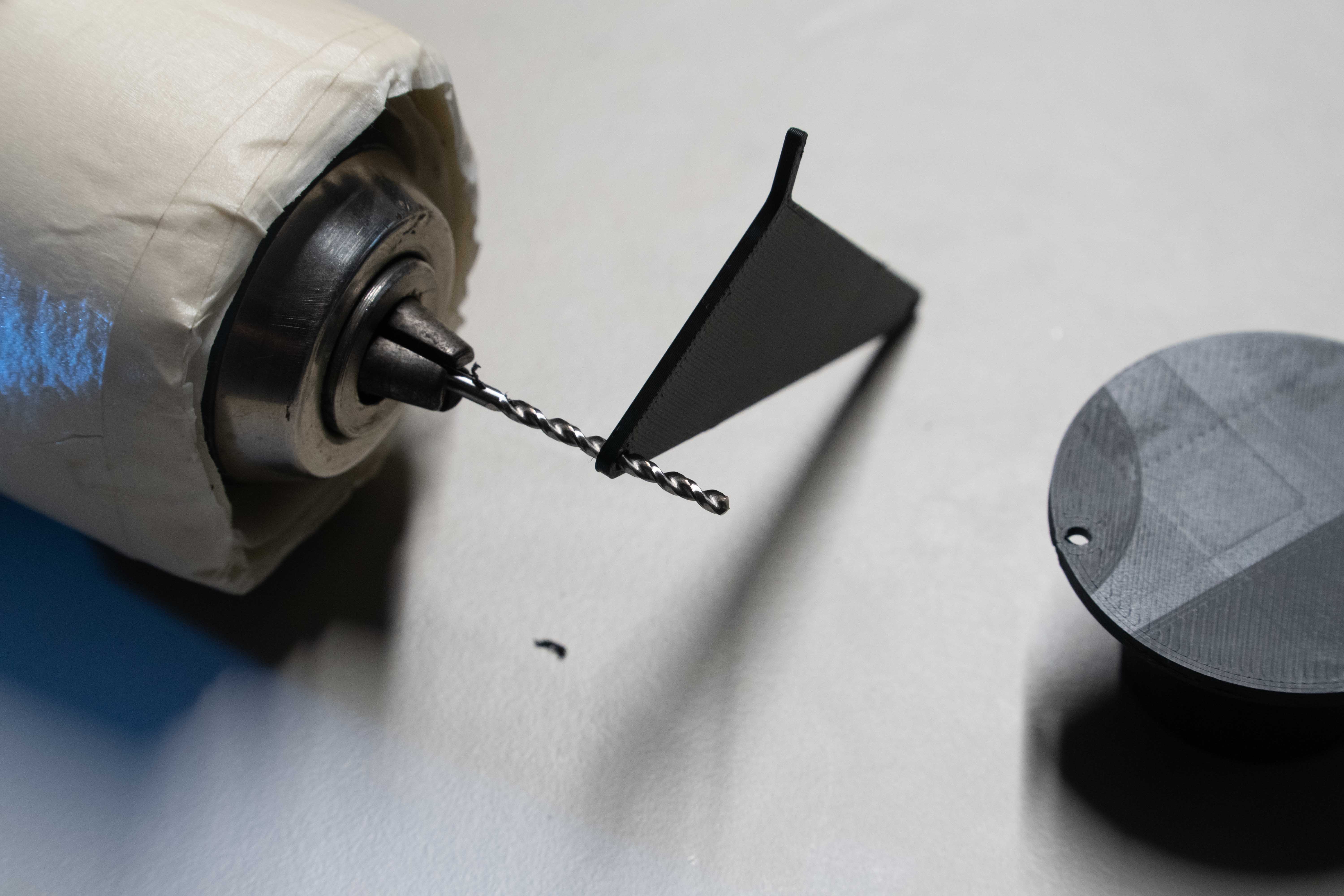
- Assembly:
- Glue the handles to the knob

- Install the crank into the top part of the main frame and screw the knob into it

- In order to assemble the hinged parts, filament rivets will be used:
- First, insert filament through the hinge

- Heat up one side of the filament with a hot air gun or a lighter till soft.

- Press with a flat piece of metal (pliers or cutters work great) while holding the filament in place on the opposite side.

- Cut the opposite side to length

- Repeat heating and pressing
- Repeat the process for the sliding joint
- For the first joint between the crank and the claw, the rivet on the side of the crank has to be pressed flush into the countersunk hole in order to allow for rotation

- First, insert filament through the hinge
- Glue the base to the top part by applying superglue on the two flat side parts of the base and activator on the top part, aligning the tabs and pressing the two parts together. (make sure no superglue leaks into the film slot)
- Glue the handles to the knob
- Tuning
- The mechanism right out of the print most probably not move the film one frame at a time like designed. This can be fixed by modifying the tip of the claw.
- load a scrap piece of film into the mechanism and look at it through the slot in the base

- The mechanism is supposed to move the film by 8 sprocket holes every time thus after one crank rotation, the claw should enter the 9th hole counted from (and with) the hole it pulled on (see image)
- in order for the mechanism to do that - if it overshoots trim the tip of the claw by a small amount every time and test

- if it moves too little (undershoots), extend the tip slightly by heating it up and pulling it out. you can also try bending it if it positions the film in the wrong spot in relation to the scanner.
- Additionally, the whole frame can be moved by approximately 5mm in order to accommodate different frame locations on the film.
- Use of mechanism:
- When everything is tuned and working, load the assembly into the scanner and feed the film in from the side opposite to the crank.
- Run a few preview scans and align the first frame. You can try using one of the cutouts to roughly align the first frame.
- Scan the first frame
- Feed the mechanism one frame forwards (1 rotation clockwise - follow the arrows); the next frame should be loaded into the scanner's field of view.
Hopefully, this helps somebody out there. If you have any trouble with assembly, make sure to leave a comment, and I will try to assist; however, from doing this process twice, the best advice I can give is to give it a good few more tries.