
Minimalistic Coordinate Frame (no MMU needed)
Obliczymy ostateczną cenę na podstawie wybranego pliku. Sprawdzisz ją i zaakceptujesz przed płatnością.
Zapisane na tym urządzeniu.

rgb = xyz; red is x, green is y, blue is z. For visualizing multiple coordinate frames / frame transformations.
- Ocena
- 0 / 5
- Polubienia
- 0
- Pobrania
- 10
- Wydruki
- 0
- Wyświetlenia
- 48
- Oceny
- 0
Aktualizacja u źródła:
Informacje o modelu
- Źródło
- Printables
- Kategoria
- RC & Robotics
- Licencja
- Creative Commons — Attribution
I work at a robotics company, and sometimes it's just nice to lay down a handful of coordinate frames in the real world to make sense of their relative transformations.
Since I only have one right hand (thumb = x, index finger = y, middle finger = z) I decided to spend some time designing a “mass manufacturable” coordinate frame model, of which I now have a decent-sized stack on my desk (and have also given a lot of them away to my colleagues :) ).
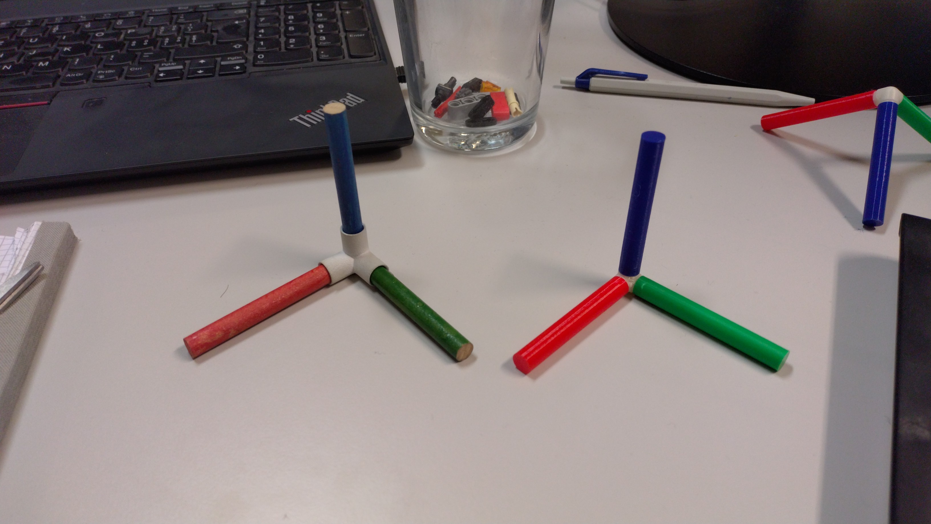
Left: Earlier version: Before I had a 3D printer I used the company's printer for a center piece, into which I inserted 3 pieces of painted wood. Right: Once I got a 3D printer for myself, everything has become plastic. It's fantastic :) !
Printing guide
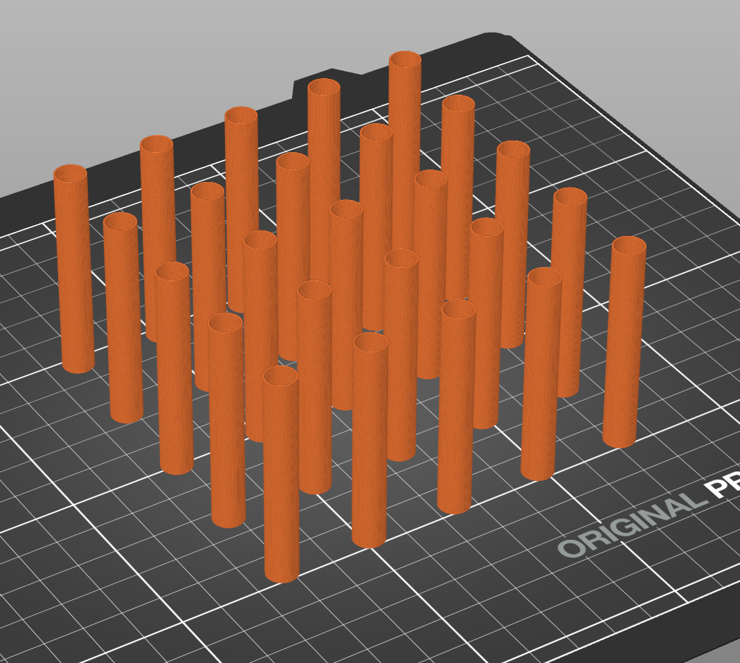
The model is meant to be printed in four separate PLA parts (one per color), though all axes are the same model. The pieces can then be simply pushed together and will hold with friction. Sometimes, the axes will break along the seam, so print extra axes, print them in vase mode, or just ignore the crack :).
- Center piece
- I used soft white PLA: https://www.prusa3d.com/product/prusament-pla-vanilla-white-1kg/
- 0.1mm layer thickness to get extra smooth roundness
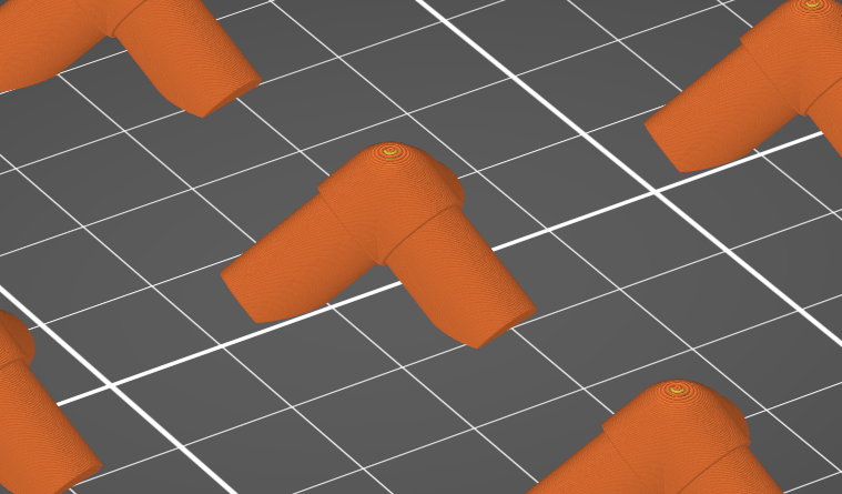
- The part is especially designed so that it can be printed “flat” and without support material, see below.
- Axes
- PLA, colors I used:
- 0.2 mm layer thickness
- If you print only one axis at a time, you can use vase mode for an impeccably seamless look, plus it should not be at the risk of cracking during assembly.
- Important: When removing the axes from the print bed, avoid “levering” them off sideways, as the bottom might pop off. Instead “guillotine” them off the build plate by sliding a flat object (e.g. another build plate) across the build plate (such that it hits the axis at the bottom and shears it off the plate on impact).
Design history
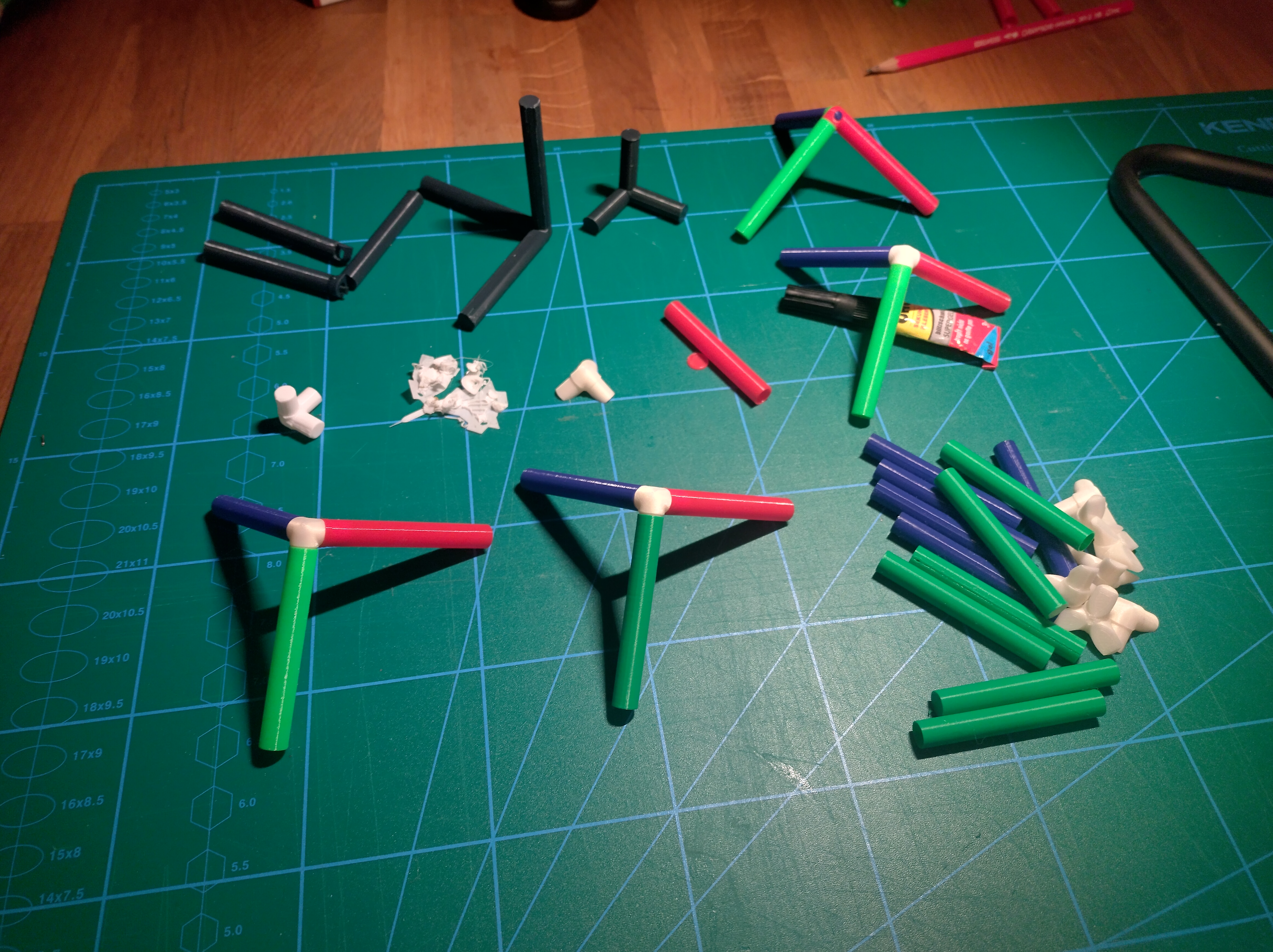
Top row: the initial design was without a central piece and unnecessarily complicated (also, didn't look as good…).
Middle row:
- The first iteration of the center piece. Turns out it's a bit ugly when printed in “normal orientation”.
- Got a lot of spaghetti when trying to print the center piece “diagonally”, even with support material.
- Turns out it's worth slicing the rods of the center piece in order to have a robust surface contact to the build plate :) .
- Learned that levering the axis off leads to breaking the bottom off occasionally. Didn't want to print unnecessary material so printed with brim for a while. That's annoying to clean up though, so in the end I instead figured out the right way to remove the axes from the build place (see instructions above).
- Early prototype didn't have the tolerances well tuned yet, held together with super glue though.
Bottom row:
- First design with good friction.
- Switched to Bambu green, looks much better!
- Mass production, baby!