
PORT NUMBERS IN ORDER! Prusa XL Filament Sensor x6 (magnetic / weaker) w/ PC4-M10 fittings & PrusaSlicer text, **Wiring Change Required
Obliczymy ostateczną cenę na podstawie wybranego pliku. Sprawdzisz ją i zaakceptujesz przed płatnością.
Zapisane na tym urządzeniu.

An All-In-One Single Sided Filament Block, utilizing the best features of all. Magnetic Single Sided Numbers in order!
- Ocena
- 5 / 5
- Polubienia
- 61
- Pobrania
- 109
- Wydruki
- 1
- Wyświetlenia
- 1391
- Oceny
- 2
Aktualizacja u źródła:
Informacje o modelu
- Źródło
- Printables
- Kategoria
- Prusa Parts & Upgrades
- Licencja
- GNU General Public License v2.0
YOU MUST SWAP SOME WIRES FOR THIS TO WORK!!!!
THIS FILE USES A CUSTOM FONT: HELVETICA NEUE (similar to prusa font) Install it before opening FILE!!
THE MODEL WILL WORK IF YOU CHOOSE TO KEEP THE SPRINGS IN THE SENSORS AND NOT ADD MAGNETS
I have both my sensors on one side and even combined into a single block, however, the out of order numbers have been driving me nuts! Of course to move the left sensor to the right side, I needed a longer wire, so instead of splicing it, I ordered one from Digikey for about $5
Molex 0151350506 - Clickmate 5 circuit 600mm
DigiKey Part Number WM16512-ND
These do come wired "CROSS" and you MUST fix this to make anything work. It comes wired
1-5
2-4
3-3
4-2
5-1
I had to change the wires originally to 1-1, 2-2, 3-3, 4-4. 5-5... but in hindsight all you would have to do is swap pins 1 and 5 on one end to make this mod work!

This image has the original layout and how I diagnosed the pinout (OLD LAYOUT)

I chose to number them in this order because of the J3 circuit board silkscreen and the bar (typically indicating pin 1) however I do not claim to be correct as to if this is technically how this connector is numbered
Swapping these wires and then RECALIBRATING THE # 4 & 5 Filament sensors is required (at least for me it was)
Pick the Left or right model and turn off “printable” for the unused one. Text is in PrusaSlicer uses HELVETICA NEUE (similar to prusa font) Install it before opening FILE!!
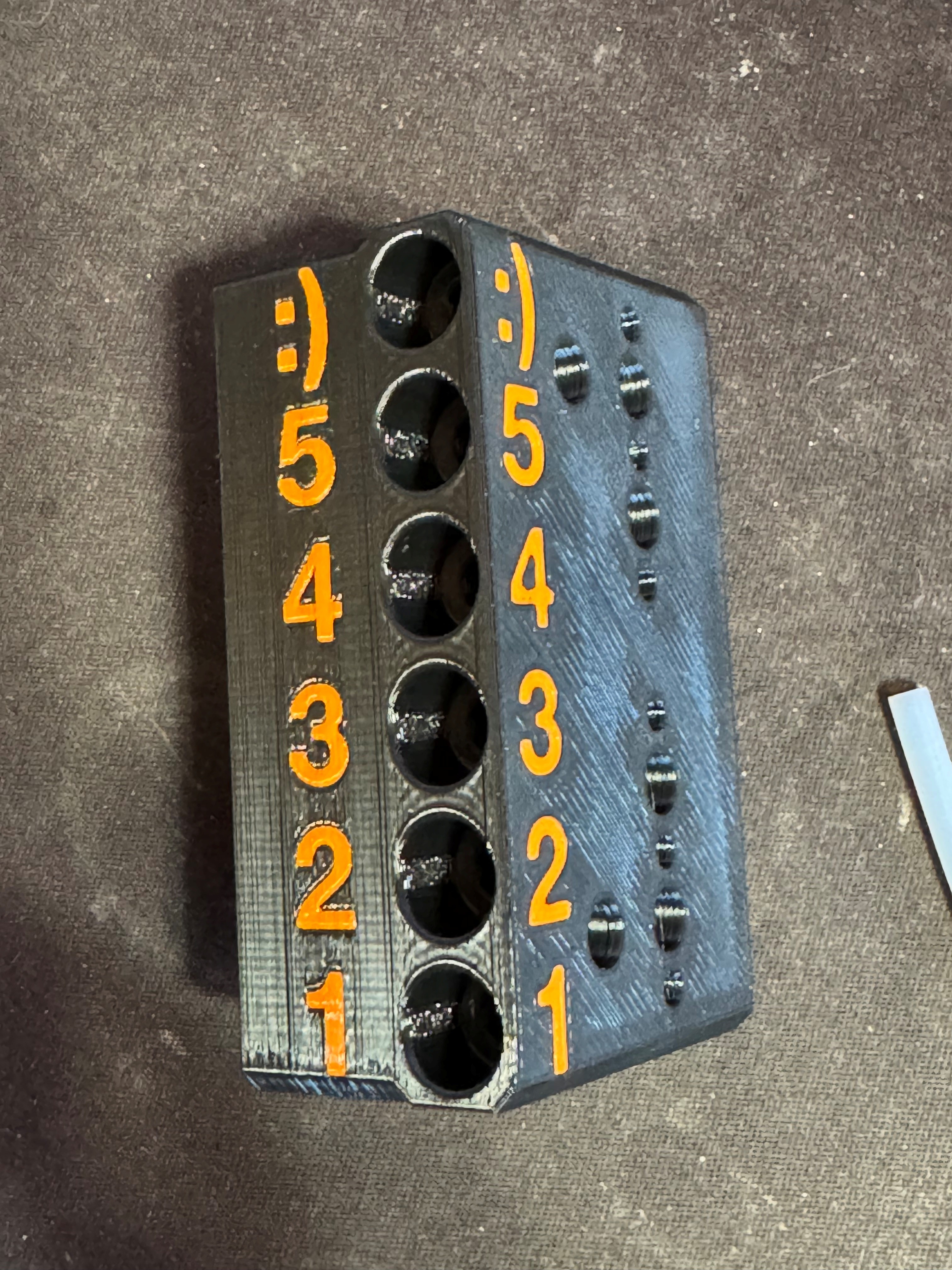
To make this magnetic vs the original springs, simply:
- remove the circuit board from the internal sensor.
- remove the spring (use a pick to get it out).
- Stand up the sensor unit (ball bearing opening upwards)
- orient the magnet so it “picks up” the ball.
- Insert that end of the magnet first into the holes on newly printed part
The original magnetic modification has great instructions
Printed in Prusament PC Blend (black and orange)
Sliced using PrusaSlicer 2.9.1 with new color interlock and single perimeter outlines on all top and bottom surfaces.