
Modular Front-Mounted 5015 Blower Modification for the Qidi Plus 4
Obliczymy ostateczną cenę na podstawie wybranego pliku. Sprawdzisz ją i zaakceptujesz przed płatnością.
Zapisane na tym urządzeniu.

A modular front-mounted 5015 blower modification for the Qidi Plus 4
- Ocena
- 5 / 5
- Polubienia
- 96
- Pobrania
- 462
- Wydruki
- 7
- Wyświetlenia
- 3932
- Oceny
- 6
Aktualizacja u źródła:
Informacje o modelu
- Źródło
- Printables
- Kategoria
- Other Printer Parts & Upgrades
- Licencja
- Creative Commons — Attribution — Noncommercial — Share Alike
Front-Mounted 5015 Blower Mod for Qidi Plus 4
This is a modular front-mounted 5015 Blower mod for the Qidi Plus 4 made for using the stock inductive bed-meshing probe, or either a Beacon or a Cartographer eddy current bed-meshing probe. Notable features are the use of a Venturi style shaping to provide for additional air-acceleration to assist with part cooling.
Photos of various installation options can be viewed at this link here.
There is a pictorial installation/assembly guide hosted here.
Update History
16-March-2025: An updated duct model named Tri-Focal-Duct-With-Baffle has been added. This has been tested to outperform the older two models which are now marked as retired/defunct.
19-March-2025: An updated beacon mount that is a little sturdier as the original model could split at the hex nut inserts under moderate pressure. This new model is around 3x stronger at that point. I also uploaded an optional, fully ducted, version of the fan mount, named Heatsink-Fan-Mount-Ducted that does a better job of cooling the hot-end heat-sink when not using a nozzle with a ceramic heat-break.
23-March-2025: I've uploaded a mounting bracket that works with the stock Qidi inductive probe. The model name is Inductive-Probe-Mount which is used for both mounting the stock probe, and providing a mount point for the 5015 blower when using the stock probe. This allows this front-blower design to be used without using a Beacon/Cartographer.
25-March-2025: I've complete uploading square metric nut insertion variants of all models.
15-April-2025: Pushed tweaked square nut models for ducted fan mount and beacon mount, with more robust screw mount points designed to support the use of M3 washers instead of just using the bare screws. This was done because when over-tightening it was possible to warp the mount points.
24-April-2025: Uploaded the recommend carrier plate model directly to this repo so that all required model files are in the one place. I also pushed a tweak to the ducted fan model which improves air-flow over a critical area of the model that is located very close to the hotend to avoid any warping due to heat there.
17-June-2025: I've uploaded a revision to the carrier plate model that makes it easier for FFF printers to print the overhanging sections. This part still retains all the important functional features, but simplifies some sections, and adjusts the angle and shape of over-hanging areas to give a cleaner appearance.
8-July-2025: Be aware that the revised carrier plate model posted on 17-June-2025 does not retain compatibility with mounting the stock part cooling fan. If you wish to continue to use the stock part cooling fan for any reason, there is now a stock fan compatible plate model posted over at my custom front tool-head carrier plate full model set here.
Introduction
Want to get rid of the build-plate exclusion zone on the back-left of the print bed? Read on!
I have provided in the model files here the best carrier replacement plate for mounting the front blower mod. Be sure to read the my custom front tool-head carrier plate model repo for instructions on how to mount and use the custom front carrier plate.
I wanted the ability to free-up the rear-left exclusion zone on the print bed that exists purely because of where the stock part-cooling fan is located.
Additionally I wanted to see if I could improve upon the stock part-cooling through the use of a more powerful aftermarket 5015 blower fan by inducing an air amplifiication effect.
Finally I also wanted to keep my Beacon (or Cartographer) eddy-current probe away from any potential collisions with the nozzle wiping apparatus at the rear of the printer.
What's Included
- A copy of the stiffer variant of the front carrier mounting plate from my custom front tool-head carrier plate repository for mounting all the front blower mod models onto
- A model for mounting a beacon/cartographer that also serves as one part of the 5015 fan mounting
- A model for mounting the heatsink cooling fan, that also serves as a duct mount, and the other mounting point for the 5015 blower fan. This model is suitable for most situations when using a ceramic heatbreak nozzle.
- An optional model for mounting the heatsink cooling fan, with the name of fan-duct. This model is intended for use with nozzles with a stainless heat-break. This model is a trickier print but introduces a fairly closed off fan duct for the hotend that does a much better job of limiting heat creep even when using a stainless heatbreak nozzle.
- An updated Tri-Focal model with adjusted internal baffle.
- (Defunct) A Bi-Focal duct that cools the part under the nozzle from two opposing sides
- (Defunct) A Tri-Focal duct that cools the part from 3 points around the nozzle
What you need to provide
- 8 of M3 x 12mm SHCS bolts for mounting the parts onto the tool-head carrier plate
- BHCS bolts may be used instead
- 6 are used for attaching the models to the tool-head carrier plate
- 2 are used for attaching the part-cooling duct to the heat-sink fan mount
- 2 of M3 x 16mm SHCS
- BHCS bolts may be used instead
- Used for mounting the heat-sink fan to the model
- 2 of M4 x 25mm BHCS bolts
- Used for attaching the 5015 blower fan to the parts
- 20mm bolts will just be long enough in a pinch if that's all you have.
- SHCS bolts may be used instead, but be wary of the SHCS bolts colliding with the glass door if left wide open
- 6 of M3 square or hex nuts
- Placed into the parts after printing
- Used for securing the various parts bolted to the models
- 2 of M4 square or hex nuts
- Placed into the parts after printing.
- Used for bolting the 5015 blower fan to the models
- An aftermarket 5015 blower fan with a standard air outlet size
- I personally recommend the absolutely amazing 9200 RPM Honeybadger
- Another awesome option is the VINDR Berserker
- GDSTime also make a great 24v 5015 blower fan
- The GDSTime blower is the fan which is in the photos.
A Note about the square nut model variants
- All M3 nut insertion channels are 2.5mm tall, and 5.6mm wide
- All M4 nut insertion channels are 3.3mm tall, and 7.2mm wide
- Try to choose nuts that are no larger than 0.1mm smaller than these dimensions
- Ideally choose nuts with dimensions 0.2mm smaller.
Unfortunately there is a lot of variation in what can be bought online. If you are running into difficulties fitting the square nuts you have into the slots in the models, then this can be fairly easily remedied by downloading the STEP file for the models and while using Fusion 360 or similar CAD software, apply the Press/Push face tool to adjust insertion channel dimensions to suit the nuts you have.
Printing Recommendations
I have created an appropriate Orca Slicer print profile which may be found here. Simply download that file to your computer and import it into Orca Slicer.
If you don't wish to use that profile, then use the follow recommendations:
- 0.2mm initial layer height
- 0.1mm layer height for rest of layers
- 5 walls
- 2mm top and bottom thickness
- 40% honeycomb infill
- Use a high temperature tolerant filaments
- eg. PC, PA, PPA, PPS.
- Use CF or GF based filaments if you have them for added rigidity
- Enable regular supports
- set to only start on the build plate works best
- Use a 0.2mm Z interface gap.
- I highly recommend NOT using tree supports (except for the ducted heat-sink fan mount, where tree supports should be used)
Printing the part cooling fan duct
It is very strongly recommended to print the ducts in the following orientation.
Position the duct on the long beveled edge and use regular (non-tree) supports. Any supports will largely do nothing anyway other than stabilise the part, and should be very easily removable.

A quick visual demonstration of how to orient in the slicer:
Printing the stock inductive probe mount
If you are not using a Beacon or a Cartographer unit, then there is a stock inductive probe mount that can be used instead.
If you use this mount, it is designed to be printed in the following orientation, which allows for the various overhanging parts to be printed with minimal support

Installation
There is a pictorial installation/assembly guide hosted here.
Note: Please use Blue Loctite, or a similar, thread locking agent to ensure that threads do not come loose over time.
Beacon Offset Config Adjustments
If using an eddy current sensing probe, the following offsets need to be applied when using this model. The following is a partial config example for a Beacon style probe.
[beacon]
...
x_offset: 14.0
y_offset: -11.0
...
and for the [z_tilt] section for a Beacon probe:
[z_tilt]
z_positions:
    -17.5,152.5
    335.7,152.5points:
   36 , 163.5
   241 , 163.5
speed: 200
horizontal_move_z: 5
retries: 5
retry_tolerance: 0.006
Note: do NOT copy the … characters
Stock Inductive Probe Config Adjustments
If you are using the stock inductive probe adaptor, then the [smart_effector] config section within printer.cfg will need to have it's y_offset field adjusted.
[smart_effector]
...
y_offset: -7           # Set y_offset to -7 to account for new probe position
...
Note: do NOT copy the … characters
Plugging in an aftermarket 2-pin fan
Qidi has blessed the toolboard on the back of the toolhead with an over abundance of fan ports. Stock there are two 2 pin fan headers that are not being used. This means you do not need to find a 4 pin PWM fan like the stock fan, it can be a ‘normal’ two pin fan if you want.

This is an example config in printer.cfg if you use “FAN 3” (outlined in Red)
[fan_generic cooling_fan]
pin:PB4              # White 2-pin fan port
max_power: 1.0
shutdown_speed:0
cycle_time: 0.010
hardware_pwm: False
kick_start_time: 0.100
off_below: 0.0
If you wish to use any of the other available fan plug ports then:
- Stock White 4-pin plug (lower right) is
pin:PA8 - Blue 2-pin fan plug is
pin:PB5 - Green 2-pin fan port is
pin:PB10
After configuring the [fan_generic cooling_fan] section correctly, then comment out, or remove, the cooling fan configuration sections referencing the fan port pin you are now using to power the blower
Removing the Rear Exclusion Zone in the Slicer
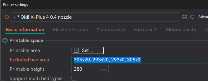
With the stock part cooling fan removed from under the print head, this means that the exclusion zone at the rear left of the printer can be removed. This can be accomplished by copying the following sequence of co-ordinates into the Excluded Bed Area configuration in the Slicer under Printer Settings, and then saving the printer config, like so:
305x20, 293x20, 293x0, 305x0, 305x20
Support
Enjoying my work? Buy me a coffee! https://ko-fi.com/stew675