
Original Prusa Enclosure - MK4/MK4S xLCD Cable Quick Release
Obliczymy ostateczną cenę na podstawie wybranego pliku. Sprawdzisz ją i zaakceptujesz przed płatnością.
Zapisane na tym urządzeniu.
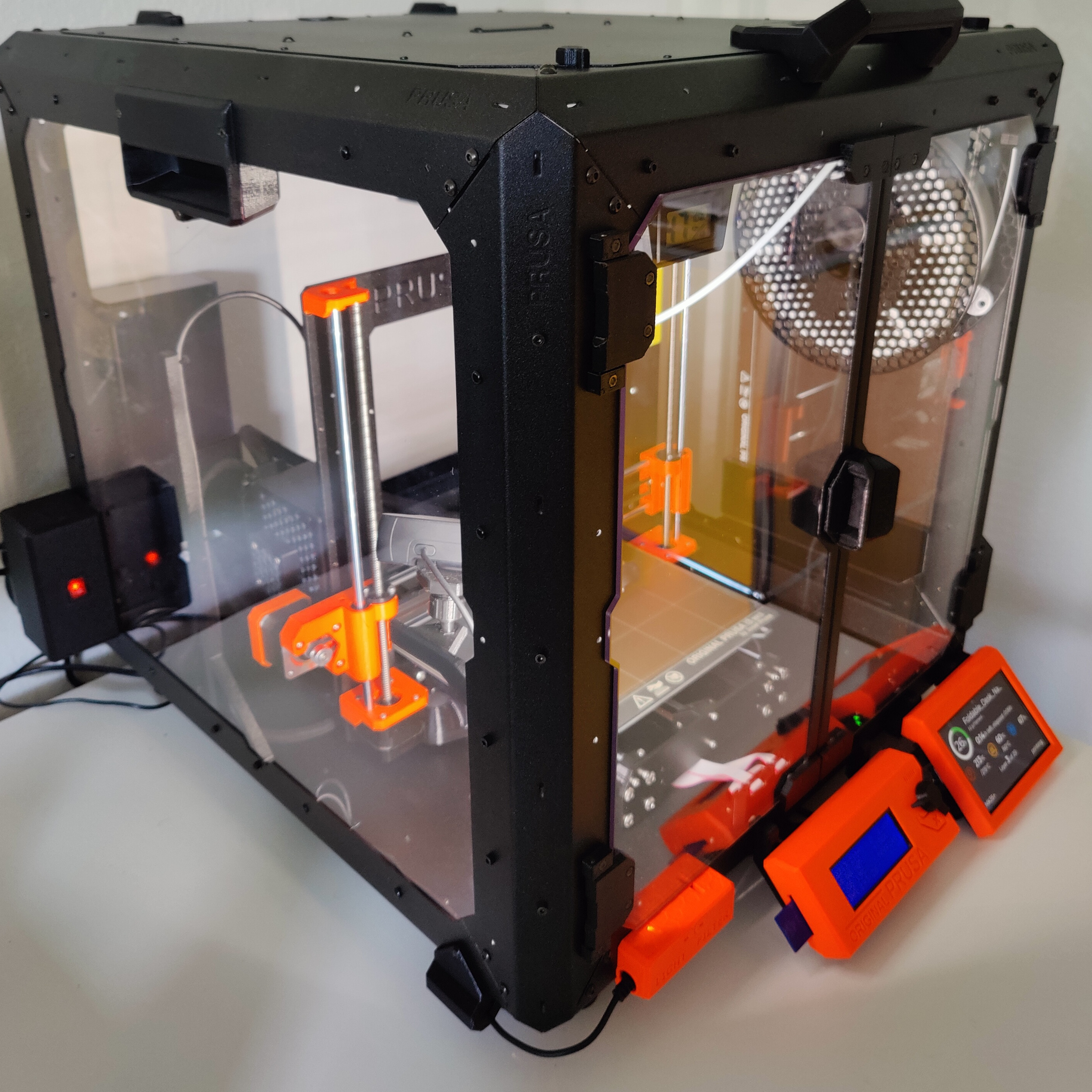
Similar to my Quick Release for the MK3S+ and the Original Prusa Enclosure (OPE). Now the version for the MK4/MK4S!
- Ocena
- 5 / 5
- Polubienia
- 14
- Pobrania
- 18
- Wydruki
- 1
- Wyświetlenia
- 389
- Oceny
- 1
Aktualizacja u źródła:
Informacje o modelu
- Źródło
- Printables
- Kategoria
- Prusa Parts & Upgrades
- Licencja
- GNU General Public License v3.0
Now that I've switched from the MK3S+ to an MK4S, I needed another Quick Release for the Original Prusa Enclosure. There are already a few quick releases for the MK4S on Printables, but I wanted another one like mine for the MK3S+ . This should also seal the hole in the enclosure better.
However, it now requires a lot more material! You need the following parts (I bought everything on aliexpress):
- 1x 24p IDC 2.54 Male Connector: https://www.aliexpress.com/item/4000669421323.html
- 1x 24p IDC 2.54 Female Connector (Box): https://www.aliexpress.com/item/1005007121852619.html
- 2x 24p IDC Micro Match Red: https://www.aliexpress.com/item/1005004993863168.html
- 2x 6.3mm Wire Terminal: https://www.aliexpress.com/item/4000173729876.html
- 2x 6.3mm Female Crimp connector: https://www.aliexpress.com/item/1005007456526329.html
- 20cm PE (Protective Earth) Cable 1.5mm2 or AWG 16: https://www.aliexpress.com/item/1005004244890241.html
- 3m 12p 1.27mm ribbon cable (I used 12p instead of 24p, so I did not have to split the ribbon cable): https://www.aliexpress.com/item/1005007535612363.html
For the model itself, you need the following screws:
- 4x M3 nut
- 2x M3 14 mm Allen Screw (for putting the top and middle part together)
- 1x M3 10 mm Allen Screw (mount on the enclosure)
- 1x M3 6 mm Allen Screw (for the wire terminals)
The model was created with FreeCAD 1.0.
For crimping the ribbon cables, look closely at the following photos and follow the instruction:
Cables from the xLCD into the enclosure and the Quick Release.
- 24p IDC Female Connector (Box) and 24p IDC Micro Match Red
- 2x 16 cm 12p cable or 1x 16 cm 24p cable
- Look for the triangle on one side of the IDC female connector, it indicates the place for the red wire (pin 1). Move the 2x p cable (or 1x 24p cable, split is not needed) from the same side into the connector, so that the red wire is at the triangle and crimp it.
- On the photo, I used 2x 12p ribbon cable.


- Look for the plastic pin on the Micro Match Red connector, it indicates the place for the red wire. Move the 24p cable (or 2x 12p cable) from the left side (when looking at the male pins) into the connector, so that the red wire is at the plastic pin 1 and crimp it.

- Crimp a 20 cm PE cable with two 6.3 mm Female Crimp connectors.
Cable from the xBuddy board to the Quick Release.
- 24p IDC Male Connector and 24p IDC Micro Match Red
- 2x 60 cm 12p cable or 1x 60 cm 24p cable (you have to split it).
- Look for the triangle on one side of the IDC male connector, it indicates the place for the red wire (pin 1). Move the 2x p cable (or 1x 24p cable, split is not needed) from the opposite side into the connector, so that the red wire is at the triangle and crimp it.
- On the photo, I used 2x 12p ribbon cable.
- For the Micro Match, do the same as above at the other end of the ribbon cable.

Replace the original cable from the xBuddy board to the xLCD, and put all parts together, mount it in the enclosure. It should look like in the photos.

