
Star Trek Print-in-Place Telescoping Fidget
Obliczymy ostateczną cenę na podstawie wybranego pliku. Sprawdzisz ją i zaakceptujesz przed płatnością.
Zapisane na tym urządzeniu.
If you love Star Trek, this 7 cm x 9 cm telescoping fidget is for you!
- Ocena
- 0 / 5
- Polubienia
- 21
- Pobrania
- 98
- Wydruki
- 0
- Wyświetlenia
- 313
- Oceny
- 0
Aktualizacja u źródła:
Informacje o modelu
- Źródło
- Printables
- Kategoria
- Other Toys & Games
- Licencja
- Creative Commons — Attribution — Noncommercial
Summary continued:
It is easy to make and even easier to play with, along with an appealing look that is sure to wow anyone who sees it! This was created in collaboration with John Quigley - @The3rdJohn_2915693 and Noah Poyau - @npoyau_2915673.
Why did we choose this design? We chose it because my group was interested in the show Star Trek and wanted something that wasn't too easy but also fun to make, and this shape fulfilled our requirements.
Lesson Plan/Activity:
By utilizing the features of sketch offsets and drafted extrusions/cuts, our objective was to model and print a print-in-place telescoping fidget. To ensure the process would go smoothly, we needed to be there for each other to provide feedback and insight into out designs and plans, supporting each other with any errors and issues we might face throughout the process. We needed to end up with identical designs by the end.
Constraints:
- The sketch must begin with a constraint box, (center-rectangle created from the origin)
- Your outermost outline must fit within an 8cm x 8cm box or equivalent area (64cm2)
- Dimensions/Relations should be efficient.
- It is not required to fully define your entire sketch, but it will help.
- The sketch must contain zero error messages.
- Demonstrate efficient use of “Offset Entities”
Instructions:
We started off by choosing a Star Trek fidget to trace the outline on Solidworks.

Using a combination of the line tool, arc tool, and circle, we reproduced the image onto Solidworks. We used smart dimensions for all of the features, which defined our lines. The sketch should fit in a box with an area of 64 cm^2

After that, we offsetted our outline a number of times, until it became so small that it would compromise the functionality of our fidget.

After offsetting, we used the boss extrude feature in conjunction with the extrude cut, and alternated the 2 features so then our fidget would start to look like this (images below). It should be boss extruded and offsetted to 20 degrees:

It should end up looking like this after completing all of the boss extrudes and extrude cuts:

Then, we used the mirror tool to mirror our shape, because it would allow for it to telescope properly. This is an essential step to our process. After this, we sketched a circle around our shape and used the feature Revolved Boss/Base, so that we would end up with a “rim” around our shape, looking like this:

And voila! There you have a 3D Star Trek fidget made in Solidworks!
Design Choices:
When creating our fidget, we faced a few setbacks.
Basic Shape:
When creating the basic shape inside the rim, we noticed that as the layers started forming, a few layers became conjoined due to the sharp points at the intersections of our lines and arcs.

To fix this problem, we needed to restart making our shape, but now changing the 2 bottom points of the shape to be rounder instead of being so sharp and pointed. This allowed for our shape to be offset correctly as the angles were not as sharp.
Outer Rim:
When we created our outer rim, we initially began to create a circle and offset it, but when we tried that, the circle would cut into our shape which would lead to the fidget not telescoping porperly as it could be conjoined with the circle.
To fix the problem, we used a new feature we hadn't been introduced to yet, the revolved boss/base. To use this feature, we needed a contruction line to rotate around, as well as the actual shape to revolve, which looked like a parallelogram.

Degree of Boss Extrudes/Extrude Cuts:
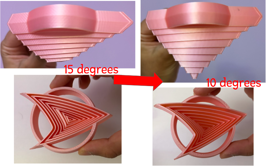
We originally started our figure with a degree of 15, as the instructions said that we were given. Once we finished making this 15 degree shape, we noticed that the degree value wouldn't work as it would likely make our figure not have much motion to telescope. We then tried 2 different versions - 10 degrees and 7.5 degrees. The 7.5 degrees was too little, and the pieces fell out of each other (video down below).

The above video was the 7.5-degree version. We then attempted the 10-degree version, which worked out much better than 7.5 and 15.

Thanks for reading! Good luck!