
Smart Chicken Feeder
Obliczymy ostateczną cenę na podstawie wybranego pliku. Sprawdzisz ją i zaakceptujesz przed płatnością.
Zapisane na tym urządzeniu.

A connected chicken feed dispenser that can be triggered via Arduino cloud or another application. Prusa Mini compatible
- Ocena
- 0 / 5
- Polubienia
- 37
- Pobrania
- 34
- Wydruki
- 0
- Wyświetlenia
- 1318
- Oceny
- 0
Aktualizacja u źródła:
Informacje o modelu
- Źródło
- Printables
- Kategoria
- Pets
- Licencja
- Creative Commons — Attribution — Noncommercial — Share Alike

What? Why?
I keep chickens since about 2 years and really love just spending a few minutes with them after I get home from work. Just to relax. I call it “chicken meditation”. I recently started live streaming my chicken camera on Twitch and to drive user engagement, I want to be able to allow the viewers to activate the chicken feeder from the stream.
But the feeder can be adapted to allow nearly any kind of integration, for example integration with Home Assistant to start the feeding as soon as the coop door is opened in the morning (door sensor) or integration with IFTTT to trigger feeding via E-Mail.
Please note: The integration to twitch is not done yet, I still need to get familiar with the twitch API but it is in the works and I will update the documentation later.
Currently it is just a simple remote control using Arduino Cloud

Hardware
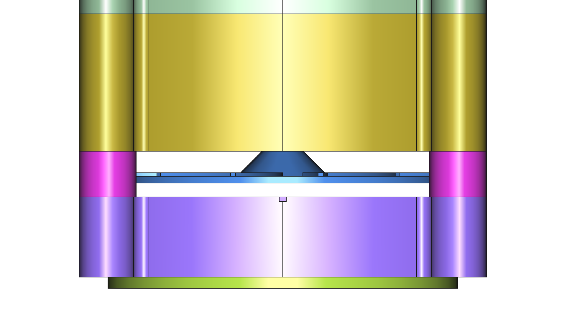
The feeder uses a rotating disc (shown in blue above) underneath a funnel, driven by a 12V geared motor, to dispense the feed. So it only has 1 moving part which makes it easy to build and maintain.
The device consists of the following parts, all held together by 4pcs M8 threaded rod:
| Top cover with screw lid |  |
| 2x Reservoir stacked |  |
| Funnel |  |
| 4x Spacer | |
| Rotating Disc |  |
Base with bottom cover The ring-groove should prevent water from entering the motor shaft-hole |  |
Parts and Materials
Bought Parts
You'll need the following parts aside from the printed parts:
| Num | Part | Link* |
| 1 | Arduino Nano ESP32 | Arduino |
| 1 | Extension for Arduino Nano (optional, makes wiring easier) | Aliexpress |
| 6 | M8 Nut | Aliexpress |
| 4 | M8 threaded rod, 500mm lenght | Aliexpress |
| 4 | M8 ring nut (eye nut) | Aliexpress |
| 4 | M3x10mm screw (motor mount) | Aliexpress |
| 8 | M3 screw, 12 to 16mm lenght (bottom cover) | Aliexpress |
| 1 | 12V 150rpm geared motor with M8 shaft | Aliexpress |
| 1 | 3.3V logic level relay module | Aliexpress |
| 1 | 12V to 5V step-down converter (make sure to select 5V output variant) | Aliexpress |
| 1 | 12V power supply, min. 1,5A | source locally |
Note: Of course you can always also source the parts locally, especially if Aliexpress is not a good option in your country because of tariffs etc.
Other materials and tools
Chances are, you have these already at home
- Wire
- Wago-Clamps (optional)
- 2-pole cable, for the 12V feed so you can place the power supply in dry conditions
- USB-C cable to program the Arduino
- Solder iron
- Basic tools
- Insulation Tape
- Threadlocker (e.g. Loctite)(optional but recommended)
Printed parts
Print settings & material
- All parts printed in PETG
- To save on material, you can reduce infill down to 5% in some areas, just keep it at 10% in the corner areas where the pressure from the threaded rod will be. Use modifier-feature in Prusa Slicer.
- Some parts need support (funnel, reservoir-top)
Printed parts list
| Num | Part | Notes |
|---|---|---|
| 1x | Feeder_Base_Cover | needs support in a small area |
| 1x | Feeder_Base | print upside down without support |
| 1x | Feeder_Disc | use Pause-Print function to insert M8 Nut into the Disc (Nut will be embedded into the print) |
| 4x | Feeder_Spacer15mm | |
| 1x | Feeder_Funnel | needs support |
| 2x | Feeder_Reservoir | Walls can be printed with 5% infill |
| 1x | Feeder_Reservoir_Top | print upside down to reduce needed support |
| 1x | Feeder_Cover_Top | print upside down without support |
| 2x | Cable gland, 12mm, use D7_L10 | Link to model, made by @93djen |
| 2x | Cable gland top nut, use D7_top-nut | Link to model, made by @93djen |
| 2x | Cable gland bottom nut, D7_bottom-nut | Link to model, made by @93djen |
Hardware Assembly
Assembling the printed parts
Solder 2 cables to your motor and mount it from below into the Base unit with 4 screws. Screw one M8 nut onto the motor shaft from above and then screw on the Disc with the embedded nut. Use the single nut as counternut. This way you can also adjust the distance between the disc and the funnel to adapt to different feed types. |  |
| Assemble the 4 threaded rods with a M8 Nut on one end, secure the nut with threadlocker (optional, but recommended for easy assembly) | |
| Take the printed Base and insert one rod in each corner, the nuts should fit into the hexagonal cutout. |   |
| Stack the spacers and the funnel on top |  |
| Stack 2 reservoirs on top |  |
| Put the reservoir-top onto the stack |  |
| Tighten the whole stack together using the 4 pcs M8 Eye nuts (will later be used for mounting the feeder) |  |
| Assemble the cable glands into the Base cover |  |
| After assembling the electronics (see below), close the Base cover with the 8 M3 screws |
Electronics
The electronics are quite simple, the Arduino controls the relay that controls the motor, no buttons etc.
The addition of a WS2812 matrix as a display is planned and this is also the reason the bottom cover houses two cable glands.
Also in the future a battery pack and solar panels could be added for complete wireless operation.
Assemble the circuit according to the below schematic:

You can also find the schematic here on Cirkit Designer.
Software V1
The software will be updated later and I will then post both variants here.
The current software uses Arduino Cloud as remote control, you can use the Arduino IOT-App on your phone or open the dashboard on your PC Browser.
The software features a adjustable feeding time and an adjustable lockout time to prevent multiple feedings in a short time.
Unfortunately Arduino Cloud does not facilitate the sharing of the complete project, so you have to setup your own dashboard and variables on Arduino cloud.
Dashboard
My Dashboard looks like this, setting up is very simple and intuitive.
Behind the feed-duration selection, each Button has its equivalent in ms assigned. The Lockout time is transferred as-is to the Arduino and then multiplied by 1000 in the code.

Sketch
You will find the complete sketch in the files section. Most of it is auto-generated by the cloud. Only a few things need to be made custom by yourself. For example the “feed”-function and “onTriggerChange”-Function:
void feed()
{
  lockout_active= true;  digitalWrite(motor, LOW);
  delay(feed_duration);
  digitalWrite(motor, HIGH);
  trigger_set= false;
  ArduinoCloud.update();
  delay(lockout_time*1000);
  lockout_active= false;
}
void loop() {
  ArduinoCloud.update();
  // Your code here
  if (trigger_set== true)
  {
    feed();
  }
  else{}
}
void onTriggerChange()  {
  // Add your code here to act upon Trigger change
  if (trigger==true && lockout_active==false)
  {
    trigger_set= true;
  }
  else
  {
    trigger_set= false;
  }
}
I know that the use of “delay” is not very elegant and frowned upon but for my V1 of the software and with the deadline for the contest approaching, I opted for this quick solution and currently it does the job.
Changelog
| Date | Description |
|---|---|
| 2025/04/22 | initial release |
Misc
Picture copyright:
All pictures: © smallthings
*Product Links
Product links may include affiliate links. The price does not change for you but I get a small commission that helps me to continue making awesome things.
Support
If you like this printable and want to support future projects, you can contribute to my next roll of filament on Ko-Fi. https://ko-fi.com/smallthings_ch