
DIN Rail Wiring System
Obliczymy ostateczną cenę na podstawie wybranego pliku. Sprawdzisz ją i zaakceptujesz przed płatnością.
Zapisane na tym urządzeniu.

A system of 3d-printed wire management parts for DIN rail devices.
- Ocena
- 0 / 5
- Polubienia
- 24
- Pobrania
- 100
- Wydruki
- 0
- Wyświetlenia
- 1593
- Oceny
- 0
Aktualizacja u źródła:
Informacje o modelu
- Źródło
- Printables
- Kategoria
- Electronics
- Licencja
- Creative Commons — Attribution — Share Alike
About
This is a system of 3d-printed wire management components for DIN rail based electrical systems.
Overview
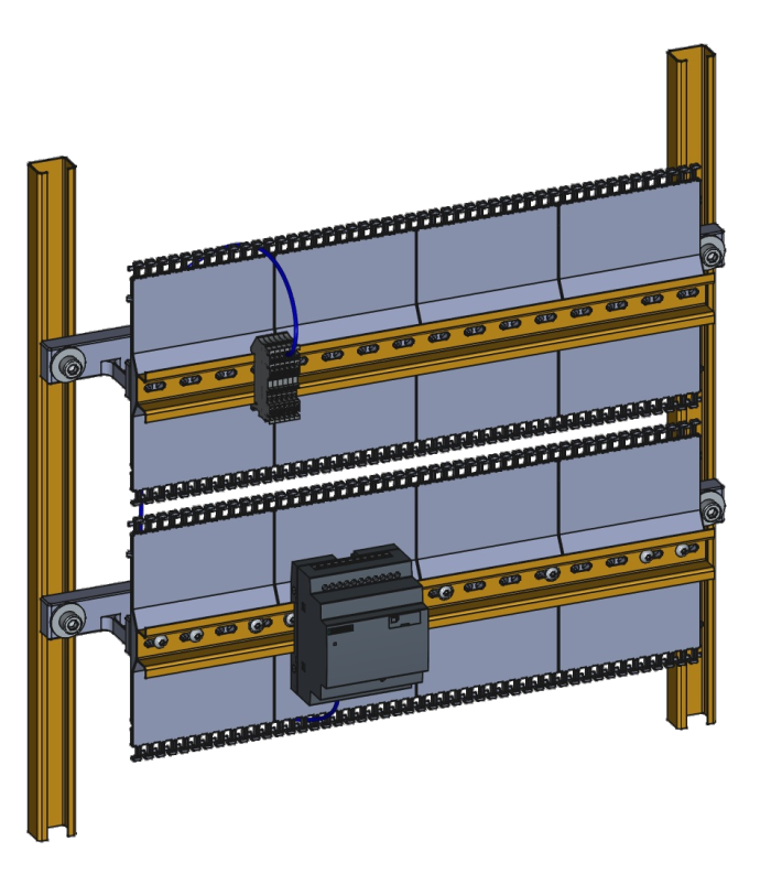
Features
- Cable combs for neat and tidy wire management
- Mounting brackets which allow running wires without ever needing to reach behind the assembly
- Different mounting options:
- Economic self-forming rib threads for low-duty use
- Heat-set threaded inserts for high-duty connections
- Options for embedded nuts as a more readily available alternative in most parts
Additional Hardware
The following additional hardware is required:
| Type | Standard | Purpose |
|---|---|---|
| DIN-rail 35x7.5 or 35x15 (35x15 is recommended for its increased stiffness) | EN 60715 | Carrier rail |
| M5x10 flanged button head screws | ISO 7380-2 | For mounting combs |
| M5x20 flanged button head screws | ISO 7380-2 | For mounting brackets and hooks |
| M5 nuts | ISO 4032 | For mounting brackets |
| M5 heat-set threaded inserts | Optional alternative mounting option | |
| Vertical support profiles (e.g. C-Profiles, Aluminum Extrusions, or even more DIN-rail) | Mounting the individual rail assemblies |
Important: The DIN-rail must be cut at “zero offset”, meaning right in the middle between two mounting slots. The length should be a multiple of 50mm.
Component Details
1 - Combs

The combs are the plates fastened behind each DIN rail for wire management.
Installation Instructions
Various fastening options are included:
- An economic rib thread for directly screwing an M5x10 screw into the plastic.
- A through-hole with a cutout for an M5 nut in the back.
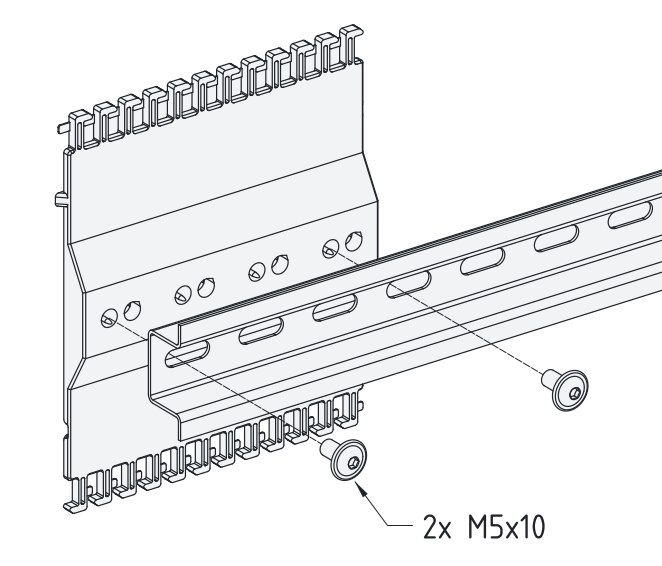
Comb Part Numbers
Comb parts are named COMB-[TYPE]-[HEIGHT]-[WIDTH]:
TYPE-H-: Standard hooks/comb for wire management
HEIGHT- Comb height. Select based on the largest device on your rail. Currently, 100mm and 150mm are available.
WIDTH- Module width. 50mm, 75mm, 100mm, 150mm, and 200mm are available.
Example: COMB-H-150-100 is a standard comb module with a system height of 150mm and a module width of 100mm. It has rib threads and through-holes for embedded nuts as mounting options.
Dimensions
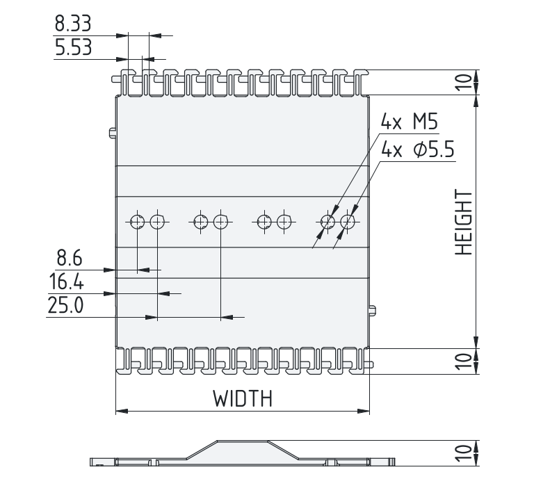
2 - Mounting Brackets

The mounting brackets allow mounting each DIN rail with combs to the support structure. They have wiring channels, designed so wires can run up and down the installation on the left and right sides of the rails.
Different types of mounting brackets are available:
U-type Mounting Brackets
U-shaped brackets for mounting the DIN rails to two vertical support profiles.
Installation Instructions
The mounting brackets are fastened behind the combs, using the through-holes of the comb. You can either push an M5 nut into the provided cutout or use heat-set threaded inserts.
When mounting, you may need to rotate the comb by 180° to align the through-holes with the mounting hook.
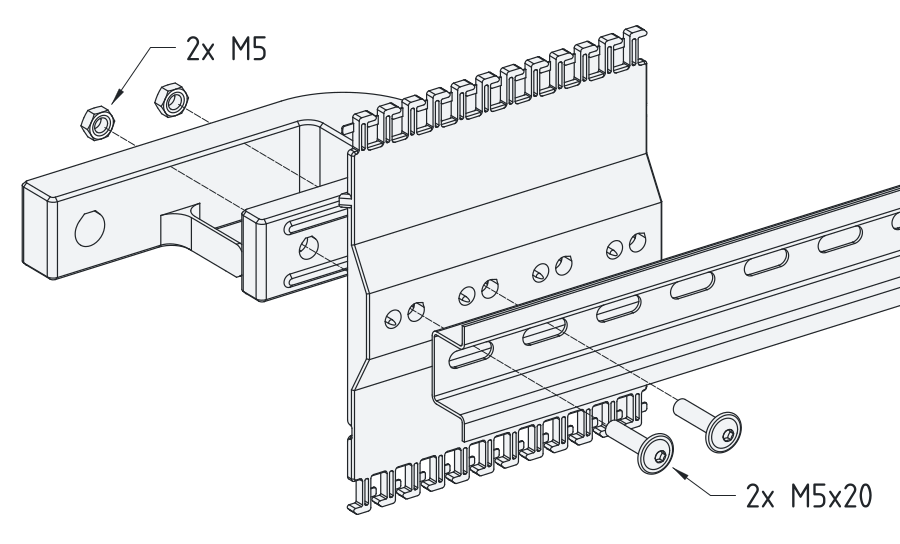
After adding the mounting brackets, the rail assembly can be mounted to the vertical support profiles as required. It is recommended to leave a ~10mm gap between the combs of neighboring rails.
Mounting Bracket Part Numbers
Mounting hook parts are named MOUNT-[TYPE]-[FASTENER]:
TYPE-U-: U-shaped mounting brackets
FASTENER- Size of the mounting fastener on the vertical support profile. Currently, M6, and M8 are available.
Example: MOUNT-U-M8 is the U-shaped mounting bracket with M8 mounting holes.
Dimensions

3 - Cable Hooks

The cable hooks are used to support horizontal runs of wires behind each DIN rail. They are mainly useful when the DIN rails are quite long and wires start hanging low.
Installation Instructions
The cable hooks are also mounted using the through-holes of the comb. By default, rib-threads are provided.
Cable Hook Part Numbers
Cable hook parts are named HOOK-[HEIGHT]:
HEIGHT- Height of the compatible comb modules. This is not the size of the hook itself.
Example: HOOK-150 is the cable hook compatible with COMB-H-150-? comb modules.
Recommended Printing Parameters
| Orientation | Print in the provided orientation of the STL/STEP files |
|---|---|
| Support Material | Print without support material |
| Layer Height | 0.2 mm |
| Nozzle Diameter | 0.4 mm |
| Perimeters | 6 |
| Material | PETG (ideally PETG V0 for fire safety) |
Finally, if you are missing a certain variant/modification, feel free to reach out.