
Electromagnetic Seesaw
Obliczymy ostateczną cenę na podstawie wybranego pliku. Sprawdzisz ją i zaakceptujesz przed płatnością.
Zapisane na tym urządzeniu.
Informacje o modelu
- Źródło
- Printables
- Kategoria
- Other Gadgets
- Licencja
- Creative Commons — Attribution — Noncommercial
Summary
It’s an electromagnetic seesaw! This is a piece of lab equipment designed to measure the force of an electromagnet on a lab scale, and includes the seesaw itself, the seesaw stand, and an arm to attach the core of your electromagnet to a ring stand.
Due to the nature of this request, these parts are designed to work with the specific equipment our science lab had on hand, so I’ll also upload the Solidworks project files for anyone who wants to make adjustments to work with their equipment, and links to where you can get the stuff it was made for. This project also uses quite a few M bolts, so you’ll want to make sure that you have those on hand.
The arm spans 57 cm wide. It takes 12.5 mm cylindrical bar magnets on one side, and 31.7 mm cylindrical weights on the other.
The stand stands at 6cm wide, 4.75 cm deep, and 8.5 mm tall.
The ring stand magnet mount holds a solid 15.4 cm long, 3.65 mm wide, and 6.2 cm tall. It fits a core approximately 2x2 cm on one side and a half-inch (1.27 cm) ring stand pole on the other.
Assembly
For this you will need:
- Parts
- One (1) arm in three (3) parts - weight side, middle, magnet side
- One (1) seesaw stand
- One (1) ring stand mount
- Hardware
- One (1) M4x45 bolt
- Two (2) M4x25 bolts
- Two (2) M4 nuts
- Two (2) M4 wingnuts
- Two (2) M3x20 bolts
- Tools
- One (1) M4 allen key
- One (1) M3 allen key
- Two (2) pairs of needlenose pliers
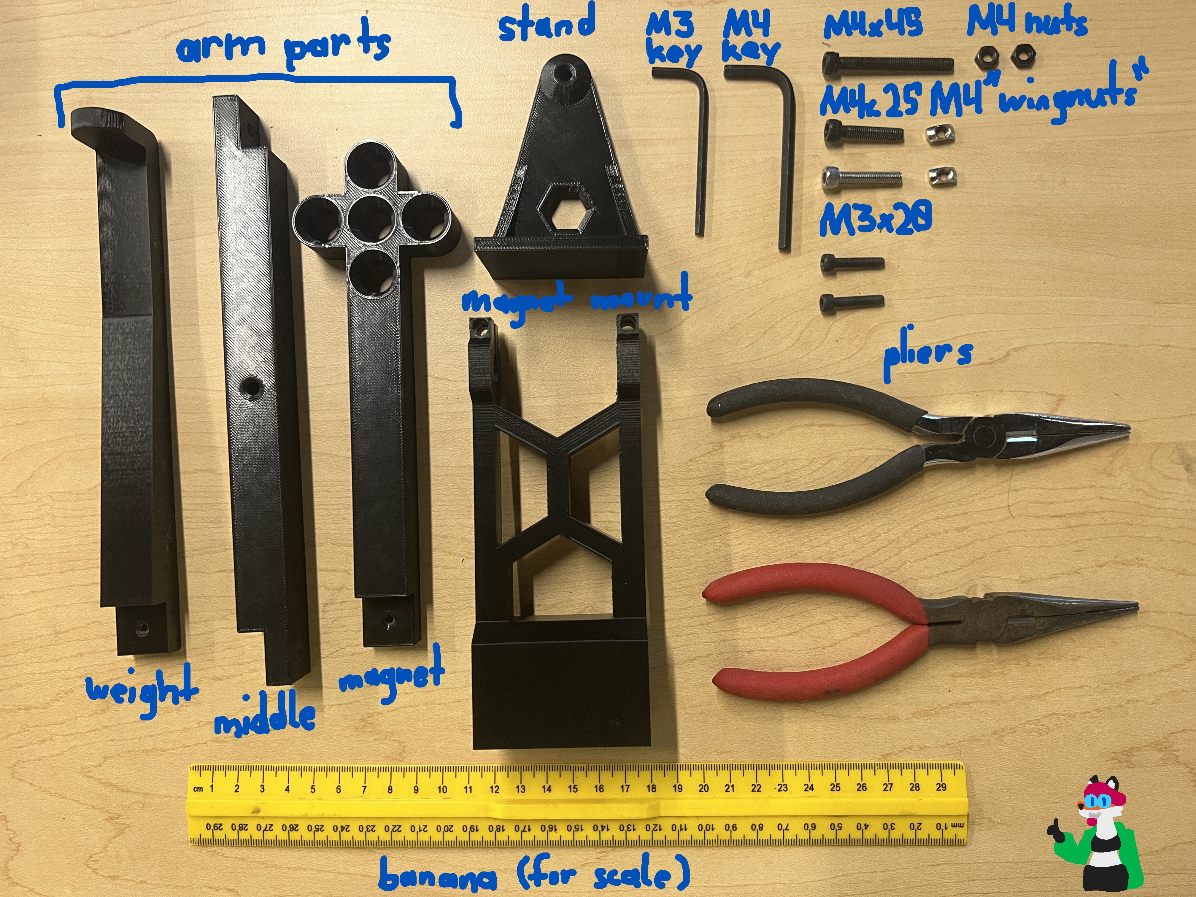
For the list of equipment needed to actually do the experiment, check the experiment itself.
Constructing the See-Saw
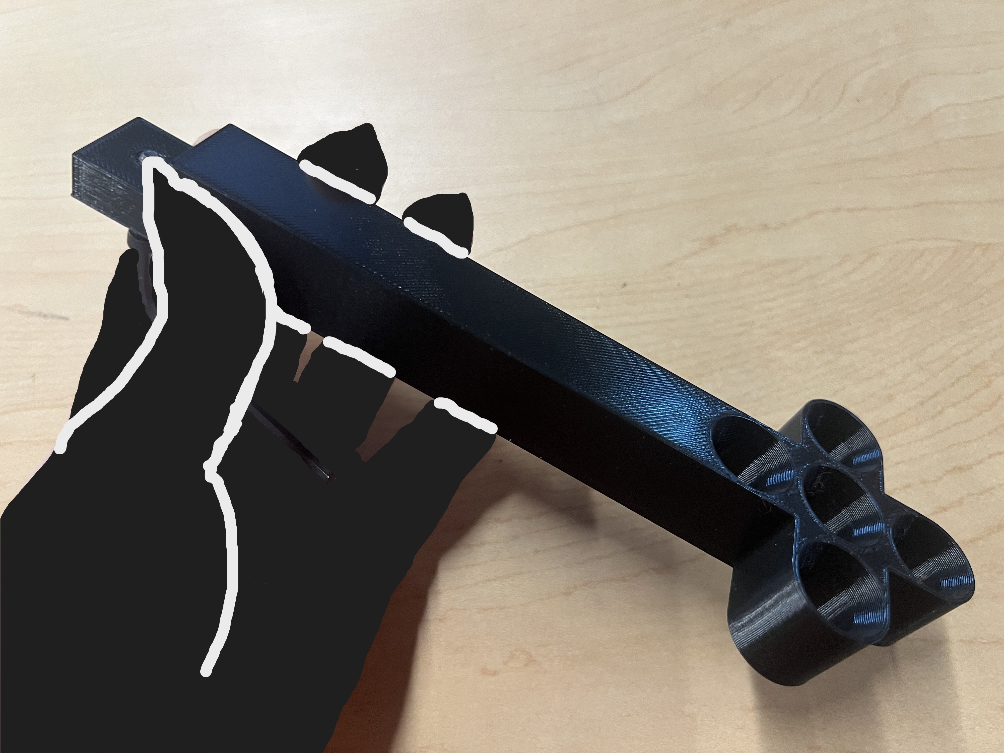
Push an M3x20 bolt firmly into the opening of the magnet side of the arm using the M3 allen key, and thread it until it pokes proud by… about 2-3 mm?
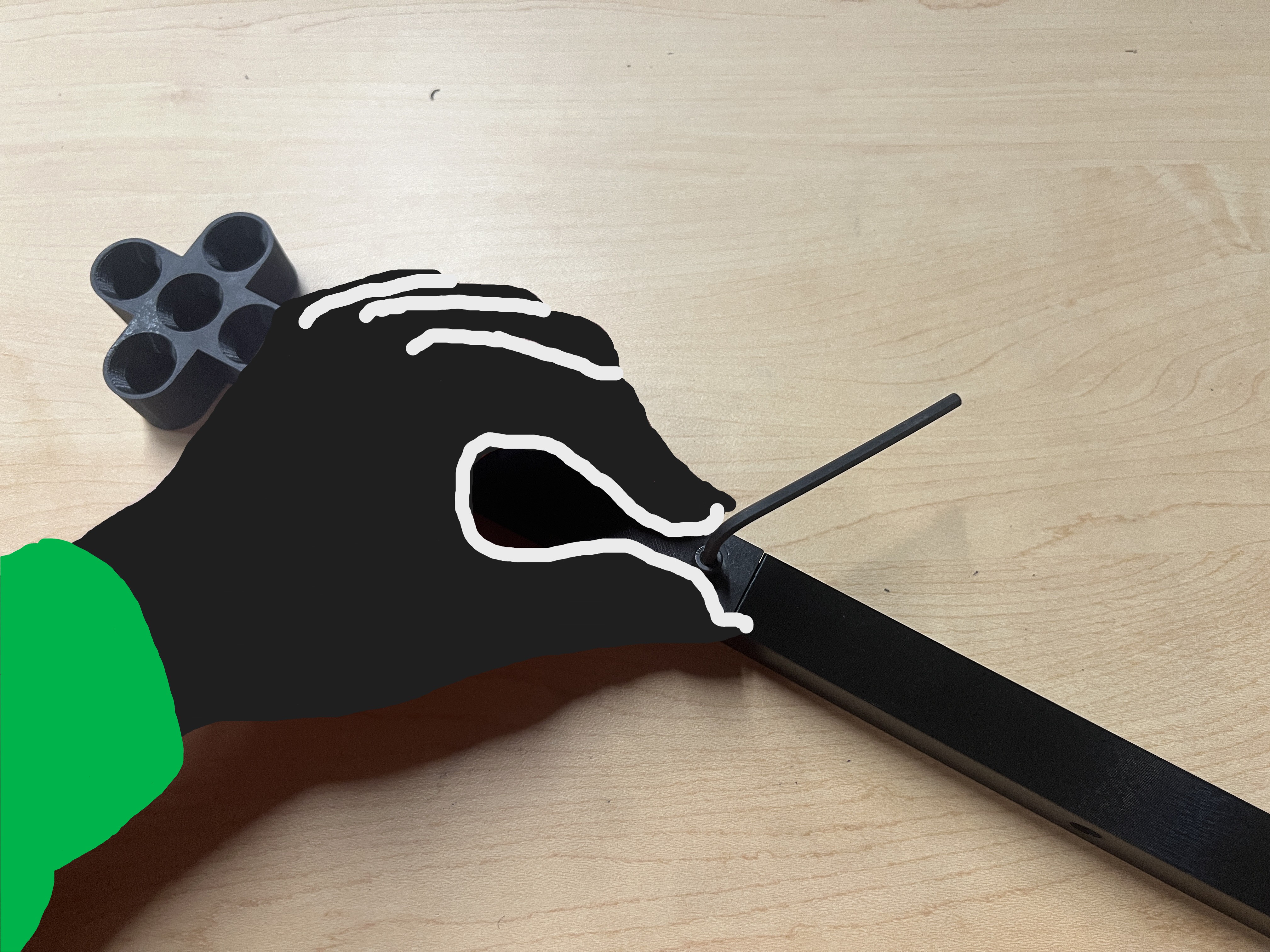
Line this proud tip up with the dimple of the middle arm part. Press the magnet arm against the table onto the middle arm (to ensure they don’t push apart) and thread the screw the rest of the way through, screwing the magnet arm to the middle arm.
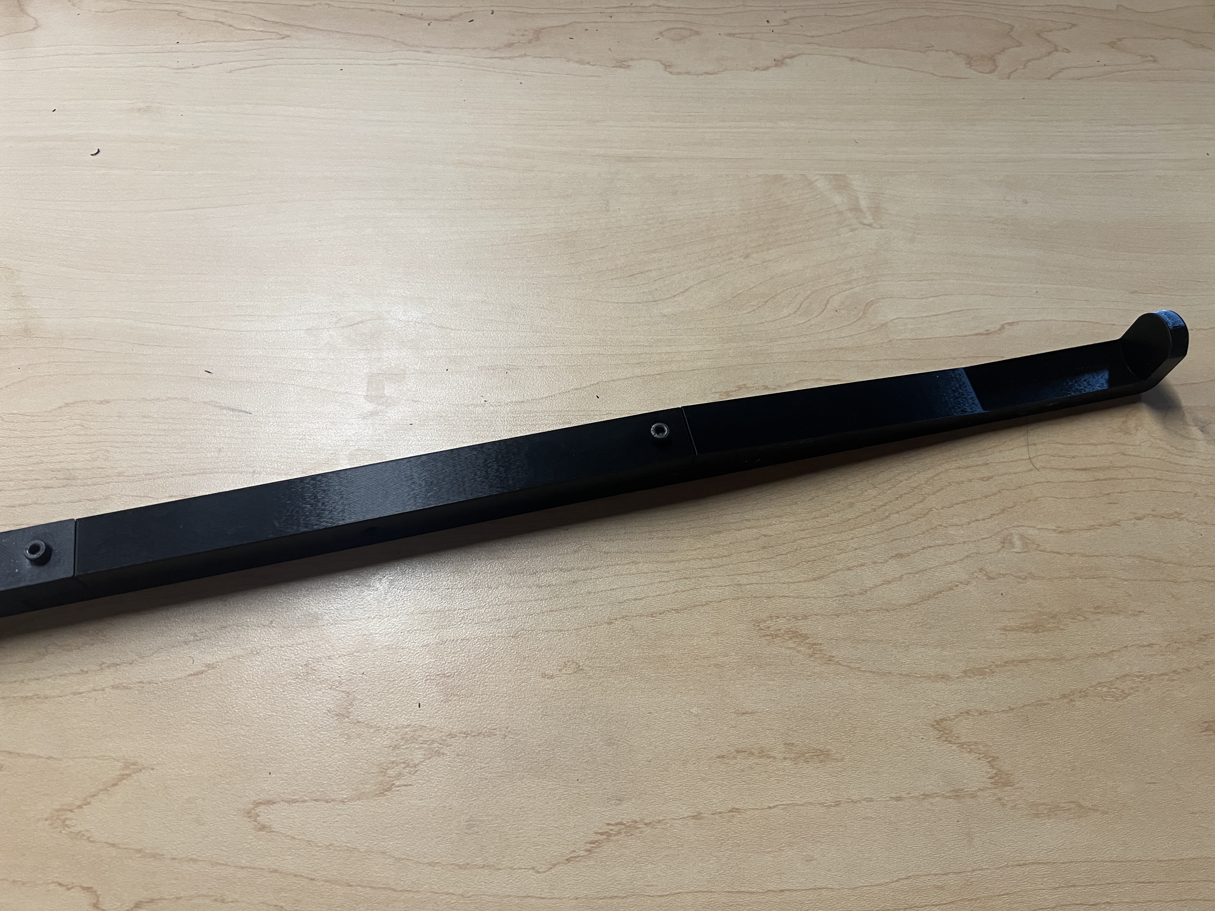
Repeat these two steps to screw your assembly onto the last arm. Make sure to thread the screw through the middle arm first, not the weight arm - the screws should be on the same side.
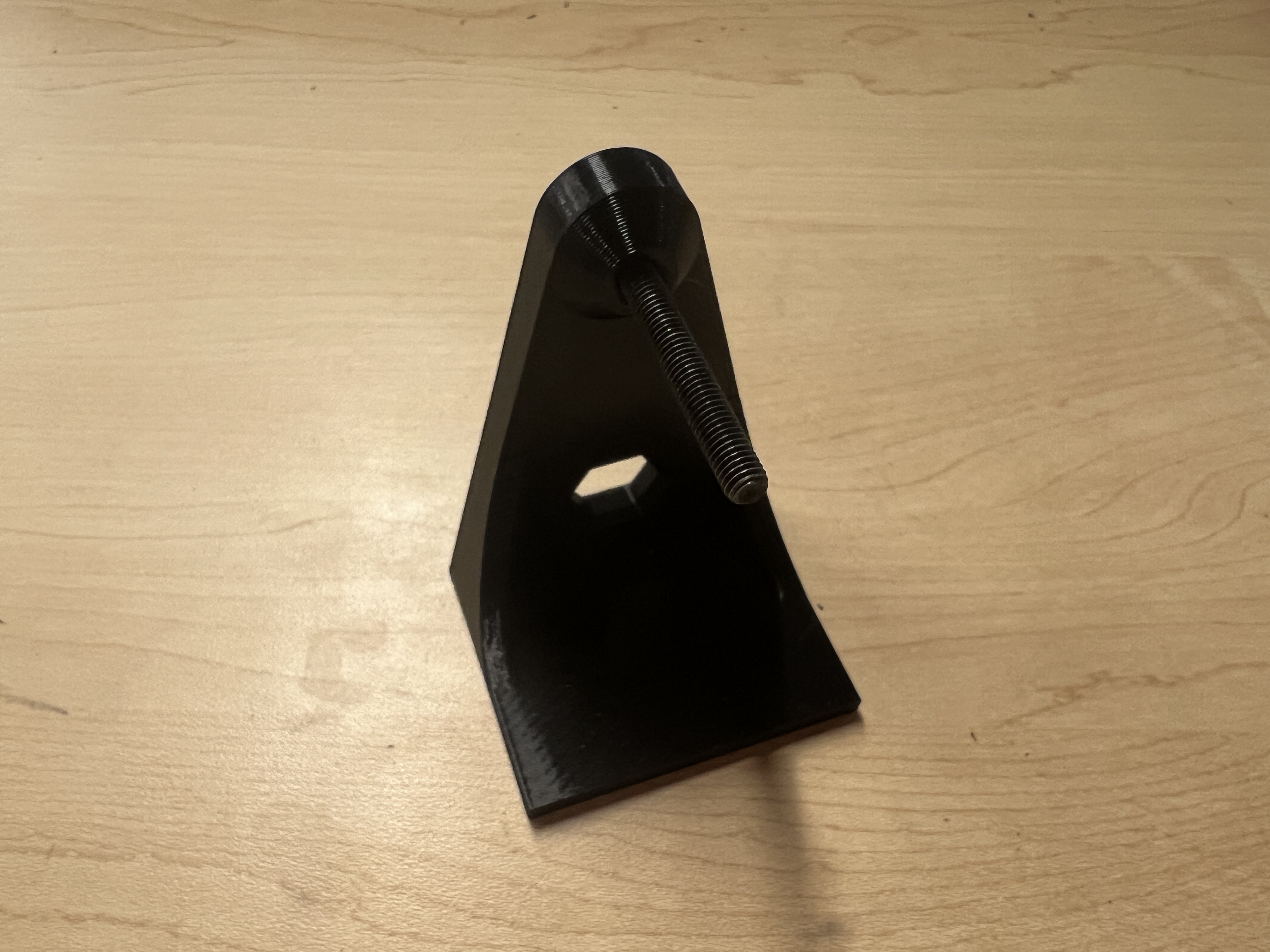
Now it’s time for the stand. Thread the M4x45 bolt through the back of its opening.
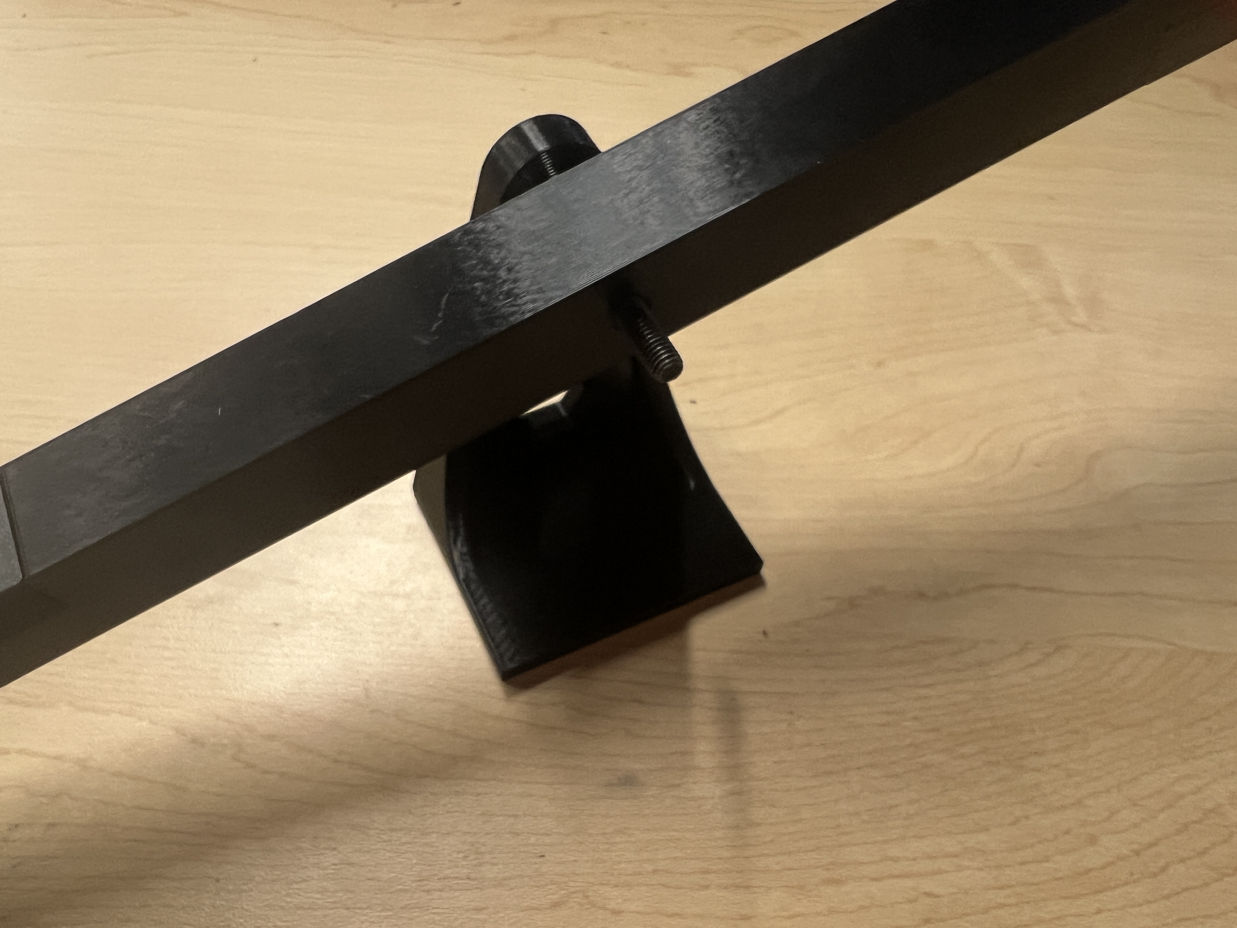
Now place the arm onto the bolt, making sure that the weight holder is facing up.
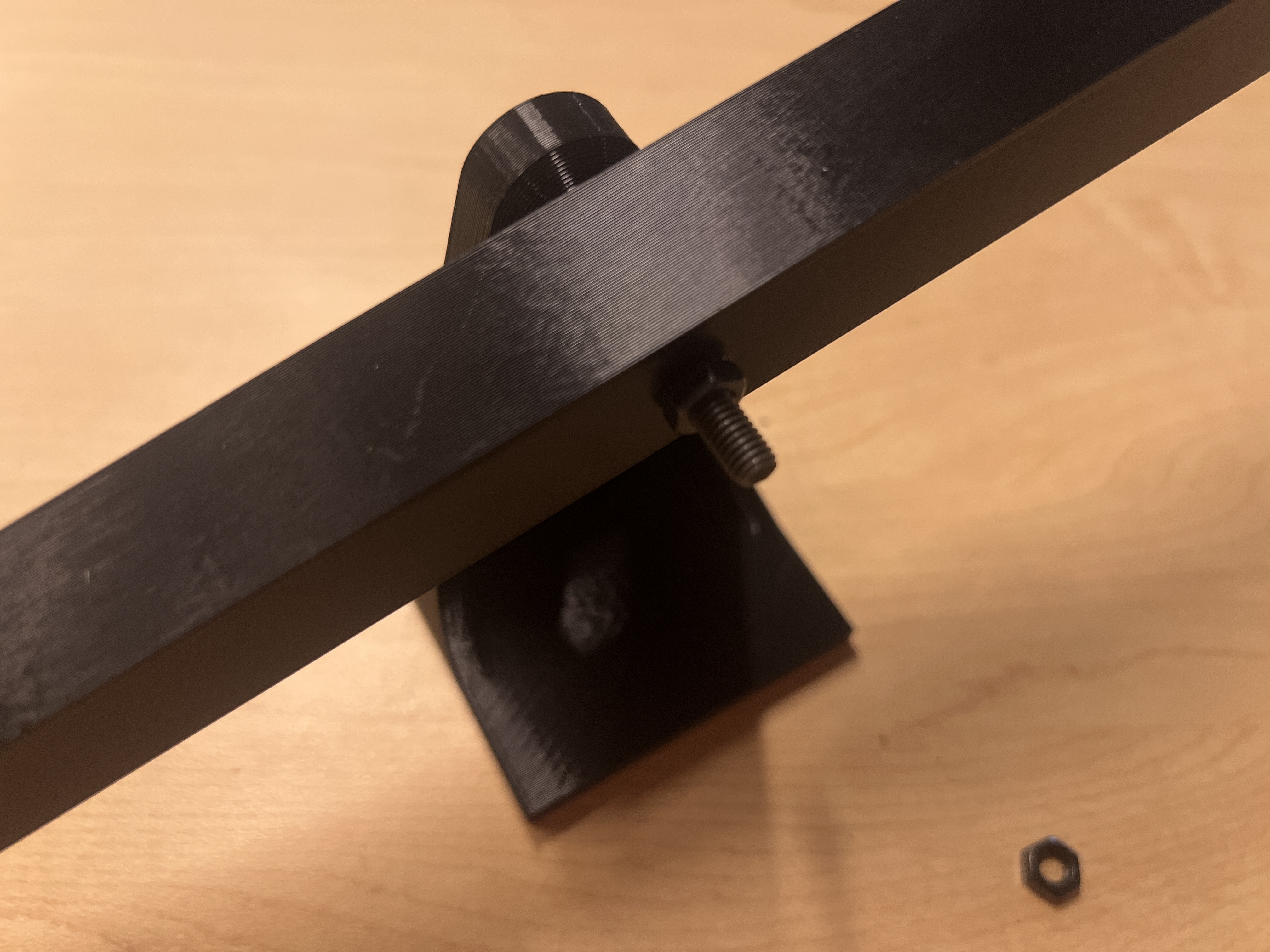
Now thread one of the M4 nuts up until it’s close to - but not touching - the side of the arm. Make sure the gap is wide enough to fit one of your pliers over it without the pliers sticking proud.
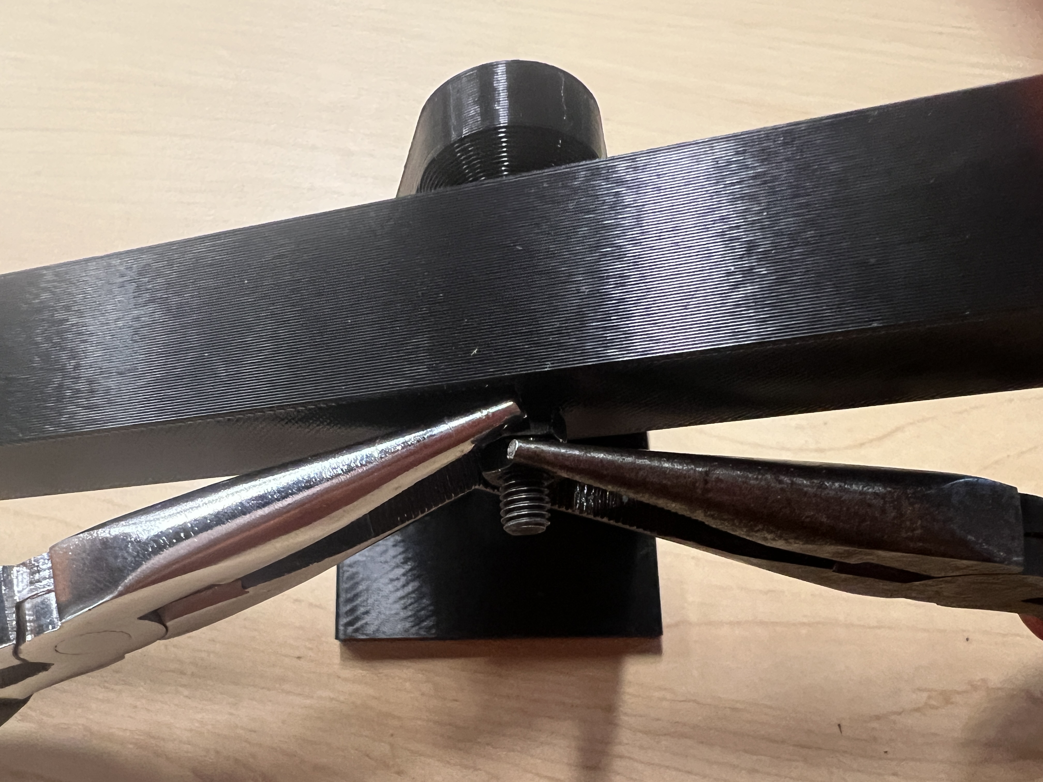
Now thread the other M4 nut up to the first, and then grab them each in a plier. It may be easier to do this if the stand is lying on its back with the bolt pointed up. counter-rotate the nuts into each other - outside clockwise (righty-tighty) and inside counter-clockwise (lefty-loosey) - so that they bind to each other.
You can check if it worked by holding the head of the bolt still and attempting to twiddle the nuts. (Don’t laugh.) If they don’t move, it worked!
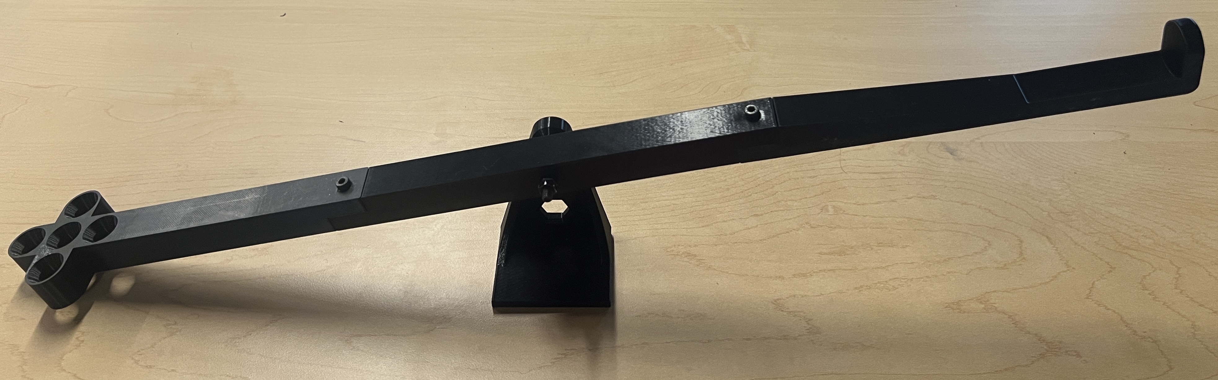
See-saw done!
Ring Stand Magnet Mount
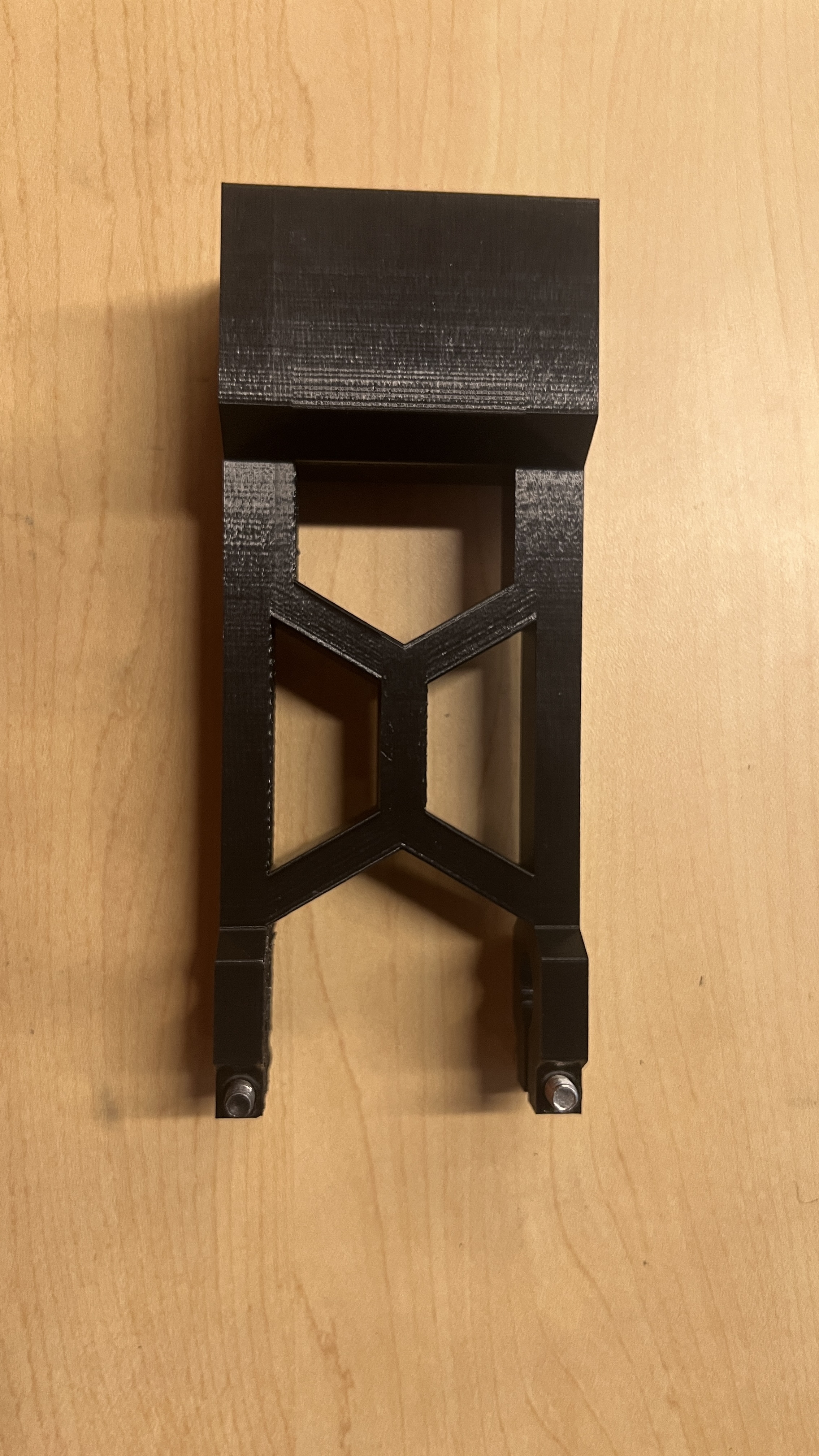
Push the two M4x25 bolts up through the holes of the mount.
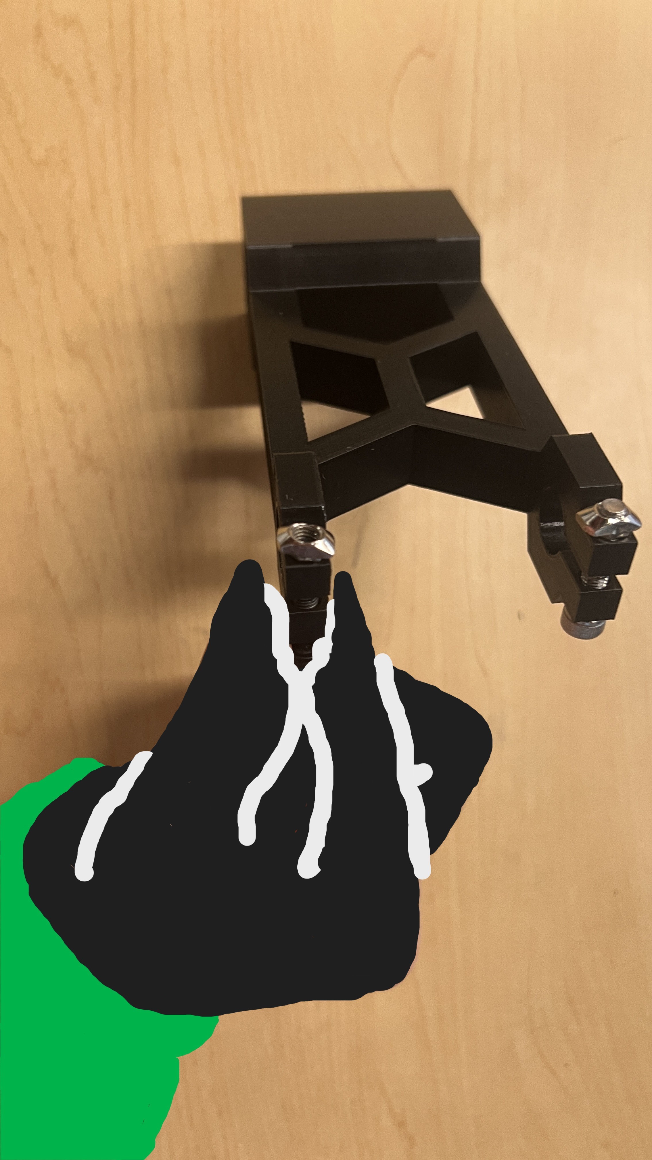
Thread your M4 wingnuts down until they reach the other side. I didn’t have actual wingnuts, so these little rectangle nerds will have to do. If you need, you can use the M4 hex key to hold the bolts still.
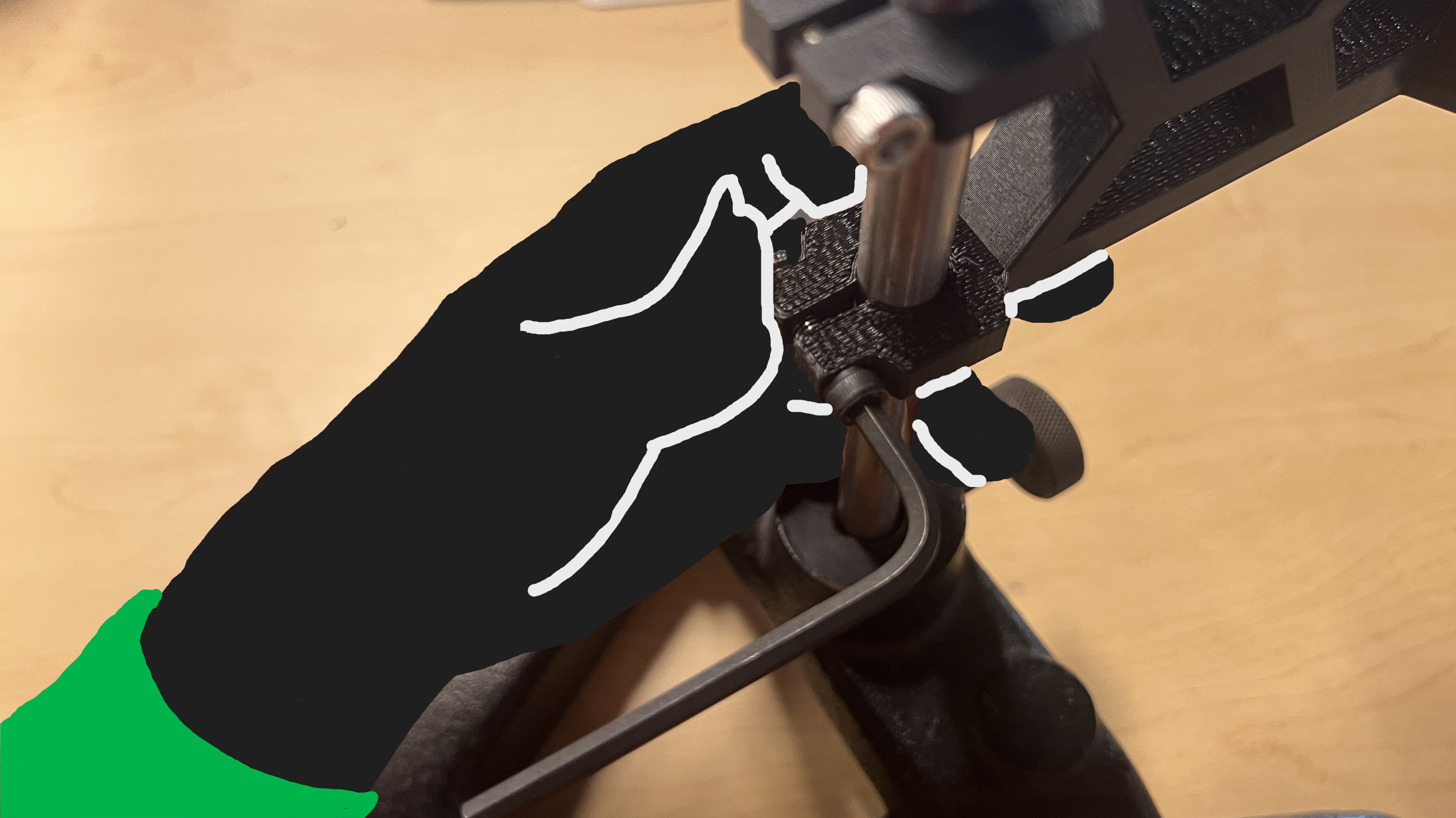
When affixing to a ring stand, use your left hand to support the mount, your left thumb to pin the wingnut still, and your right hand to tighten the bolt with an M4 allen key.
Magnet mount done! Much easier than the seesaw, huh?

Assignment
One of the physics teachers wanted equipment for a science lab that would use a seesaw arm to transfer the force of a magnet onto a scale, allowing the force to be measured. I also needed to put a hexagon in it somewhere, since that’s kinda my signature. The Electromagnetic Seesaw™ does so with an arm that holds weights to pin it to a scale on one side, and slots for magnets on the other to be acted on by an electromagnet.
Here’s how to do it!
You will need:
- Your finished set
- A ½ inch ring stand
- An allen key
- Duct, masking, or painter’s tape
- An electromagnetic coil kit
- A DC power supply
- 2 banana cables
- Up to 5 cylindrical ½ inch magnets
- A scale that can tare
- 1 ¼ inch weights
- A duplex electrical outlet
- A notebook, probably
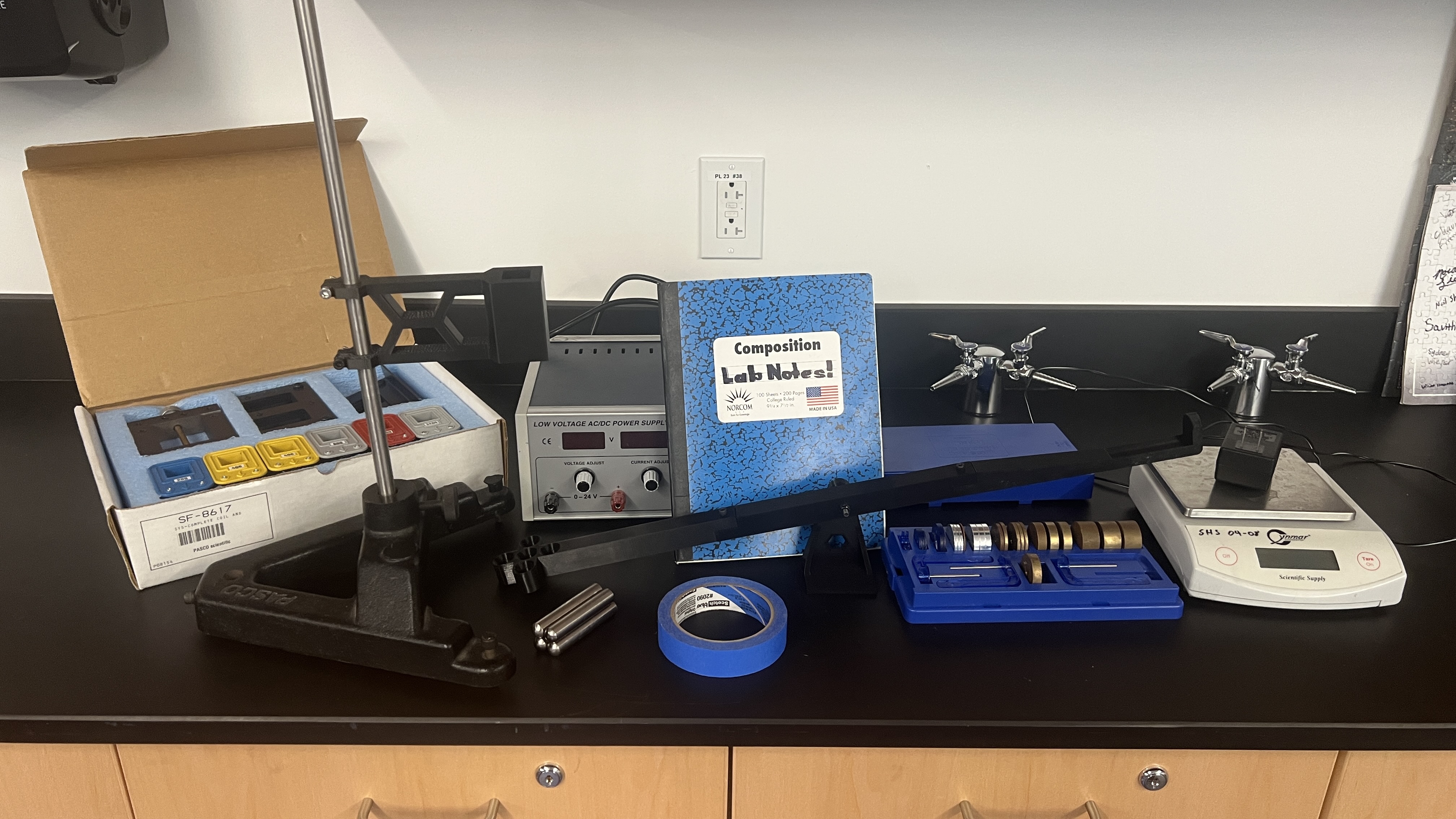
First, tape the seesaw down to your bench so that it doesn’t move. Close to the front, but not too close. I didn’t tape it enough, and taped it too close.
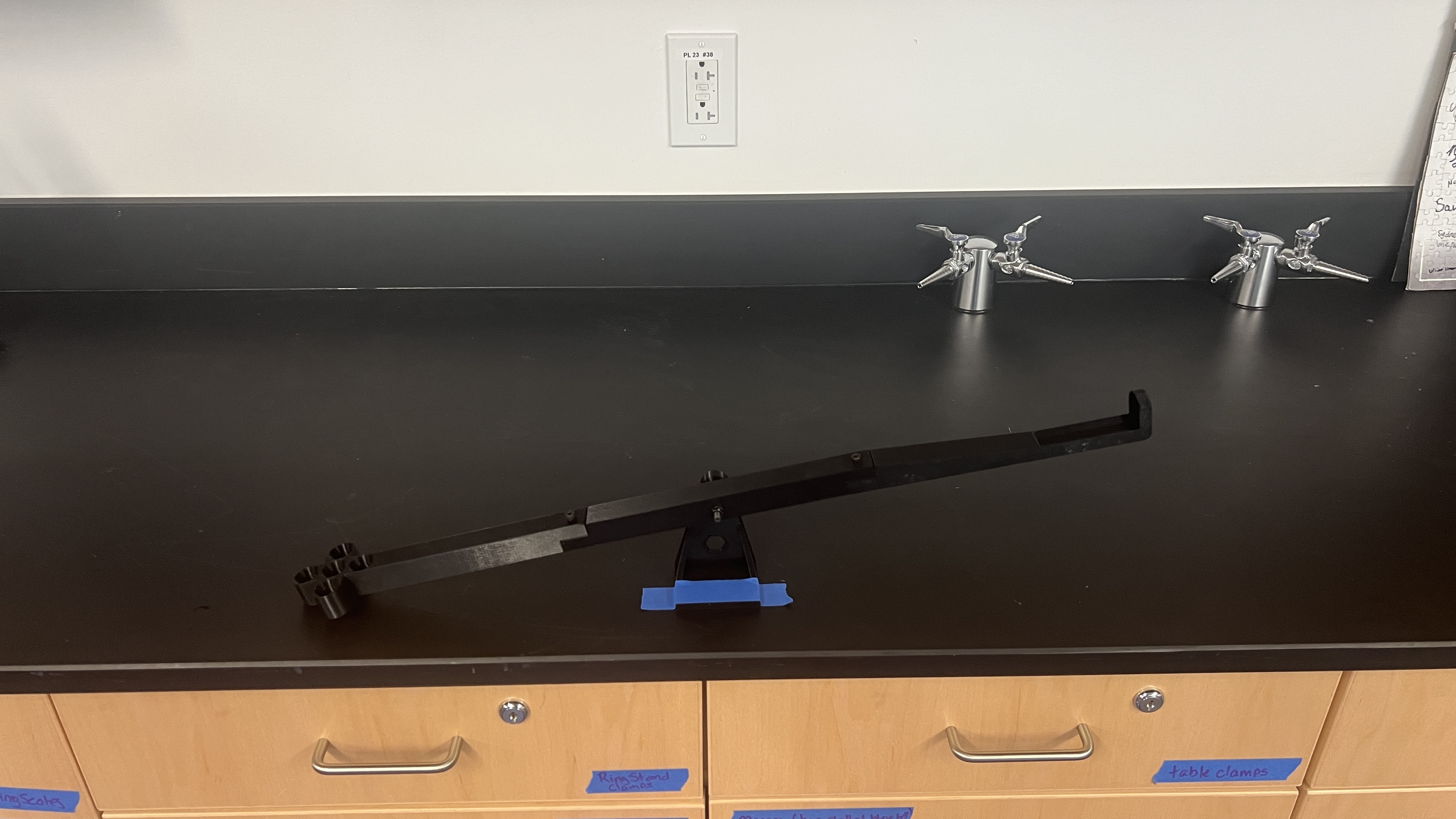
Put the magnets into the holes of the armature. If they don’t quite fit, you can bodge it with a little tape.
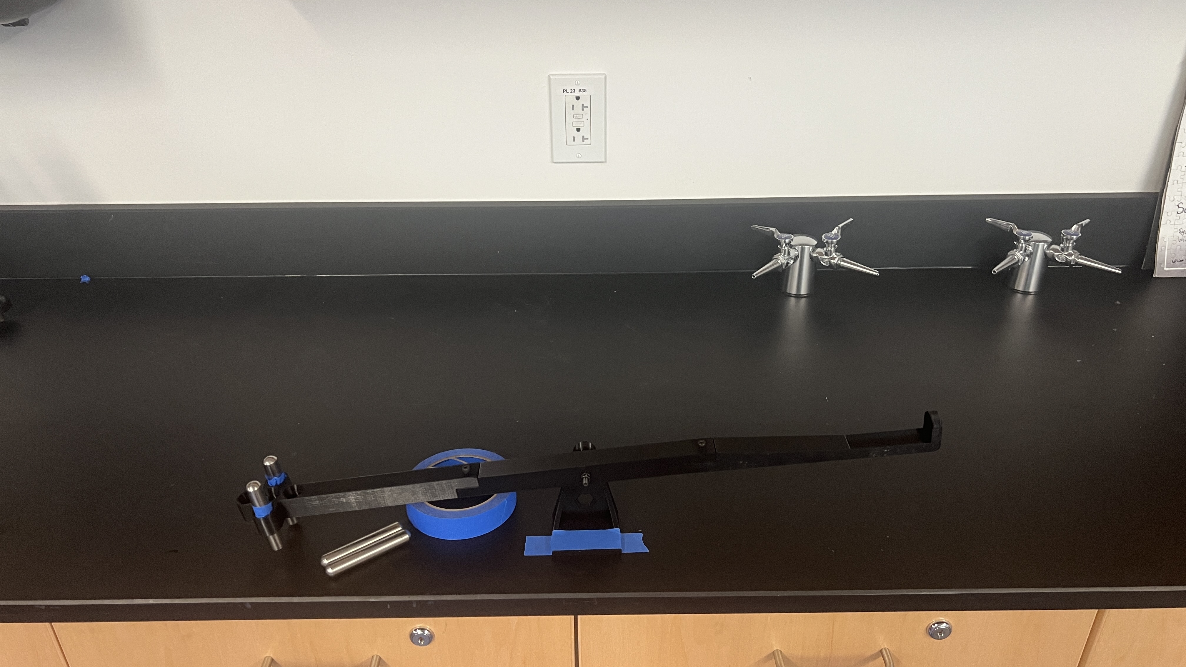
Get the ring stand and attached electromagnet mount, as well as the core and an electromagnet of your desired winding. See assembly instructions for how to attach the electromagnet mount.
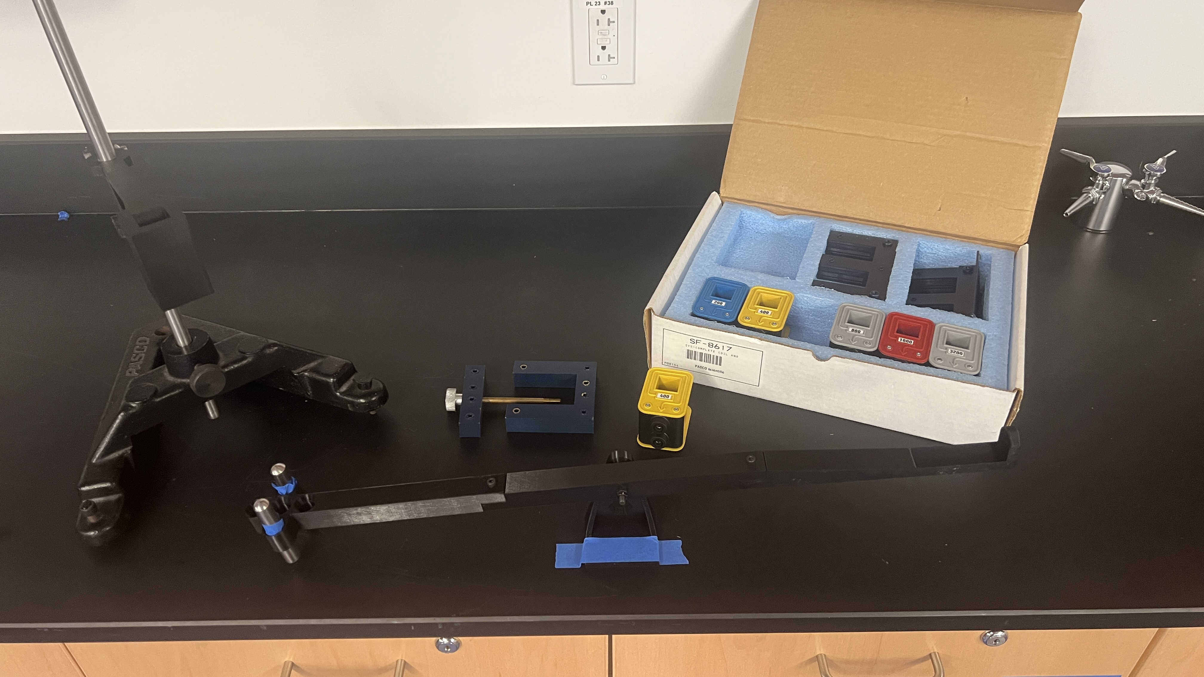
Put the coil in the core and clamp it through the hole of the stand, like so. Put the coil box off to the side.
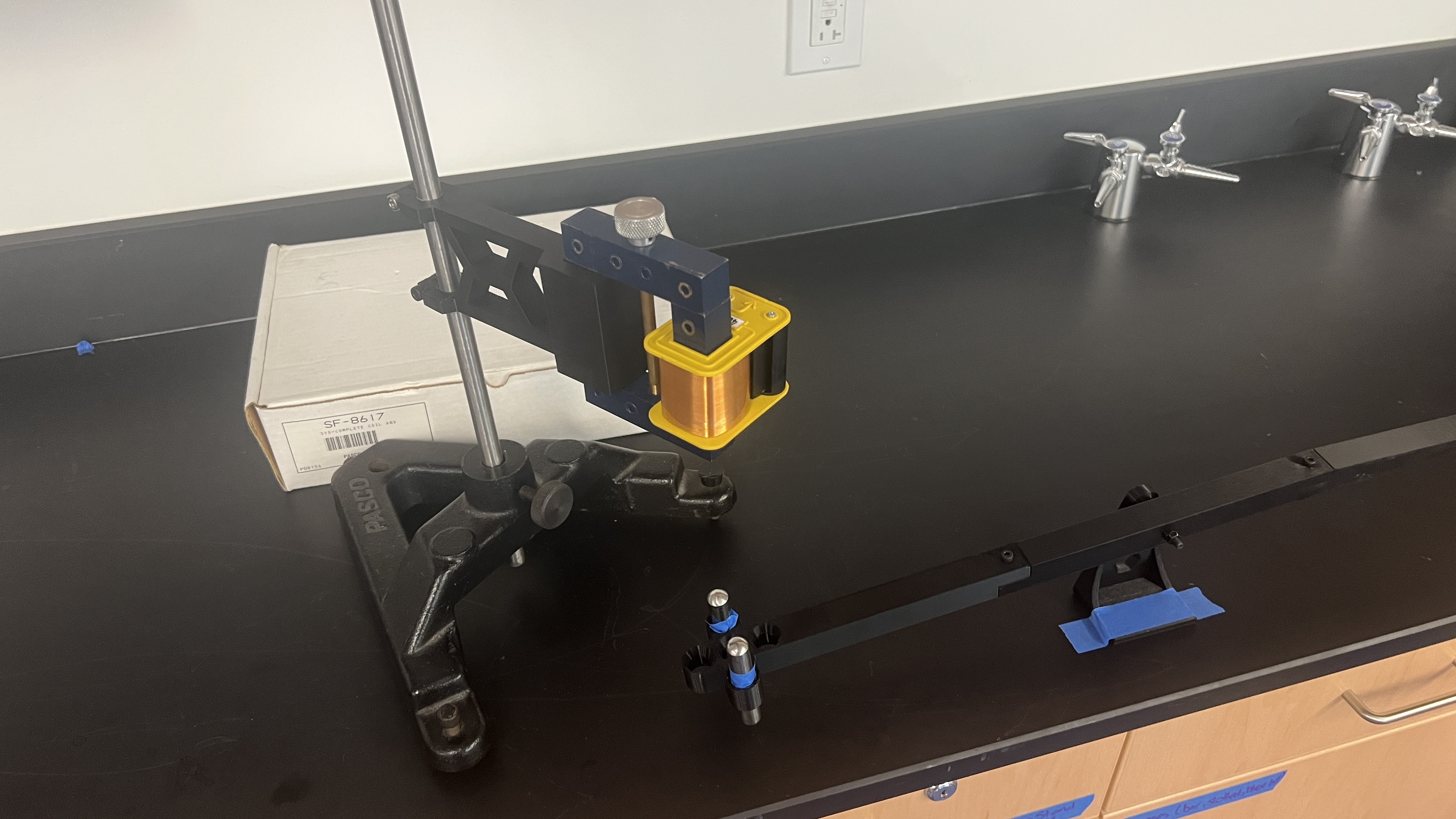
Plug the coil into your power supply (switched OFF, safety is important!) using the banana cables. Notice: I reinforced the tape holding down the stand. This is because I stink.
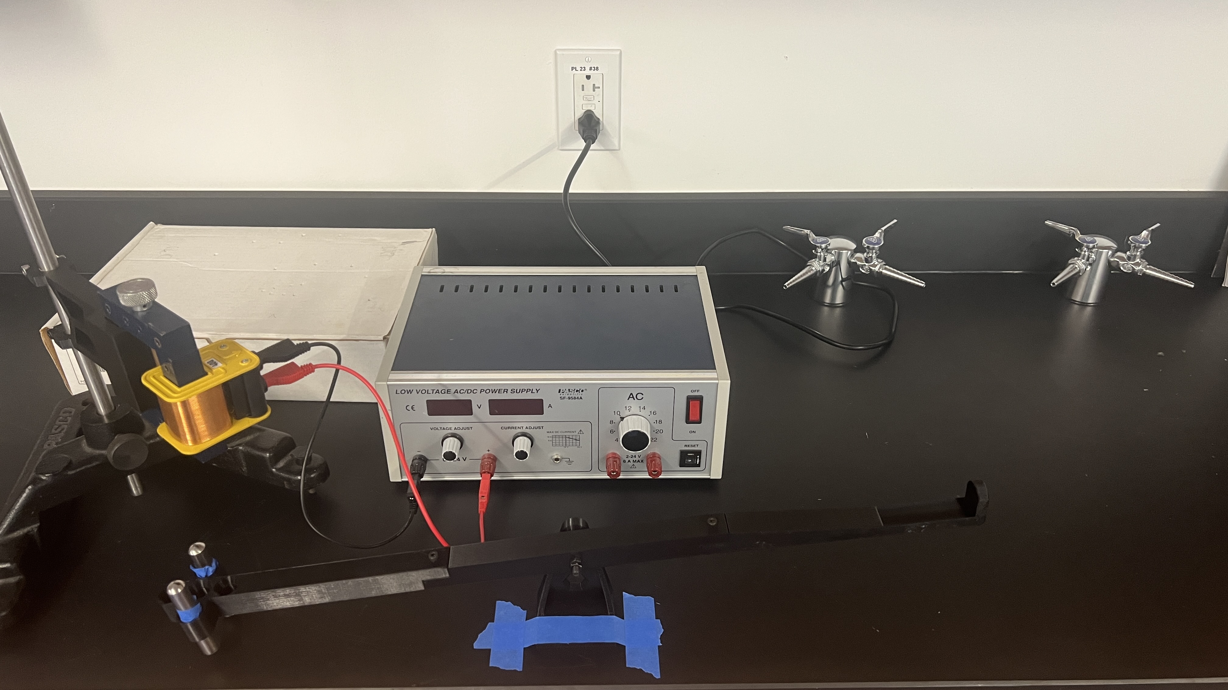
Now place your scale under the counterweight side of the arm and add 1 ¼ inch magnets until it rests on the surface of the scale. Now you can position the electromagnet over the magnet arm. Finally, tare the scale. Make sure you do it after positioning the electromagnet, as the permanent magnets are probably gonna be slightly attracted to the solid iron core. Notice: I moved the scale backward. This is because I’m a dingus.
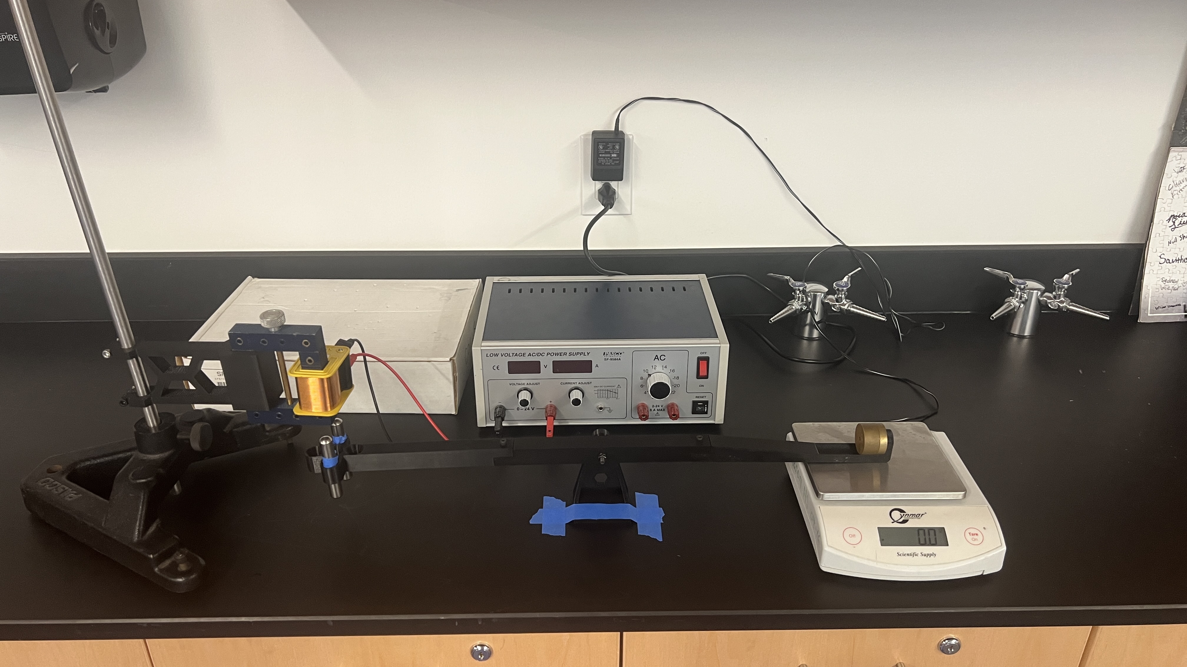
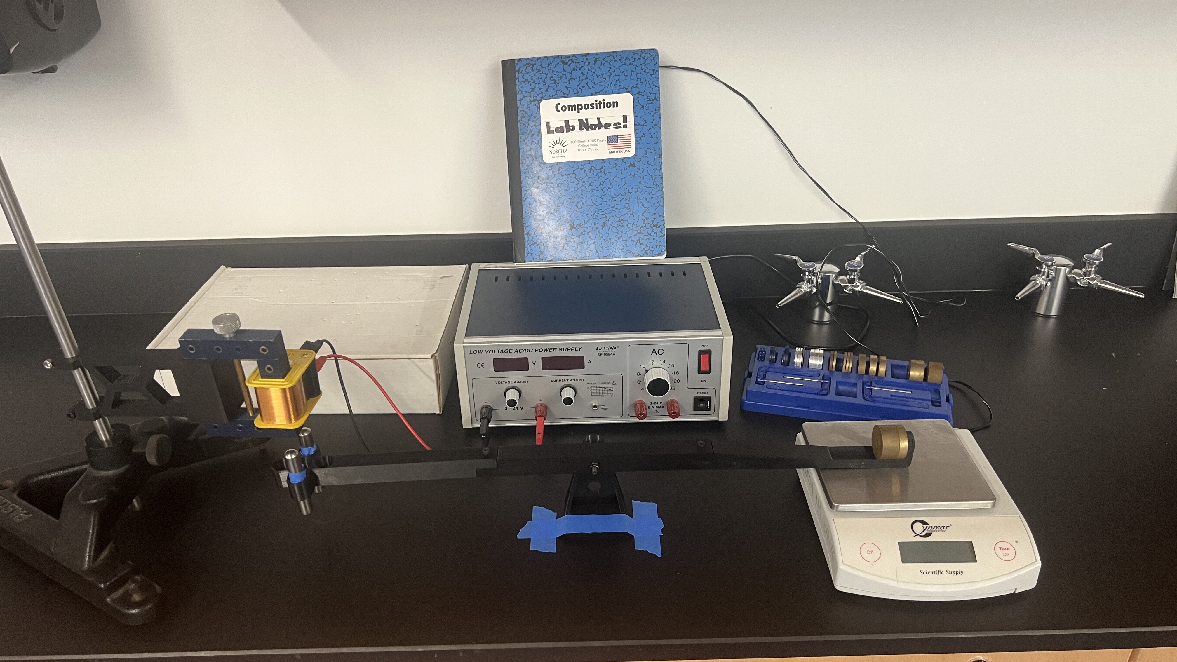
…aaand you’re done! SAFETY WARNING: THE COIL GETS VERY HOT ESPECIALLY AT HIGHER CURRENTS. DO NOT LEAVE THE POWER SUPPLY ON IF YOU’RE NOT ACTIVELY MEASURING SOMETHING. You can experiment with the control and independent variables by changing:
- Coil winding
- Power supply voltage
- Number of permanent magnets
- Polarity of the electromagnet
Design
The assignment was to make a see-saw that could press down on a scale on one side, and suspend magnets to be attracted by a static electromagnet on the other. Here are some sketches me and a partner made to flesh out some ideas.
First page!
Most of the sketch pages were double-sided, and will thus have 2 pictures.
Page 1a
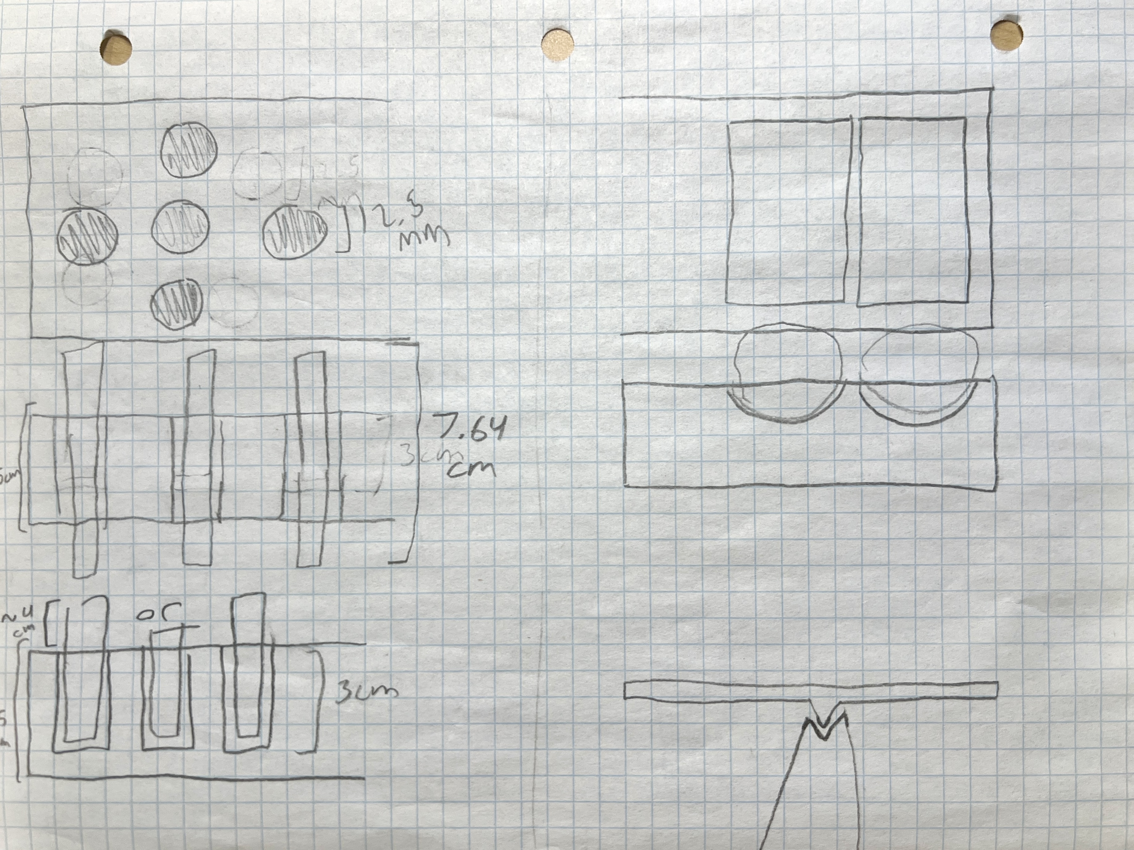
Left: Contemplating a friction or cradle-based system to hold the rod-shaped magnets. The friction system is actually close to what I went with.
Top right: Troughs to hold weights on the scale side of the arm. The weights are to weigh down the opposite side of the arm, opposing the weight of the magnet and pinning the arm to the scale.
Bottom right: an idea for a pivot-point style seesaw fulcrum. This got axed immediately, due to concerns of being able to retain and steady the arm under the forces of a lab.
Page 1b
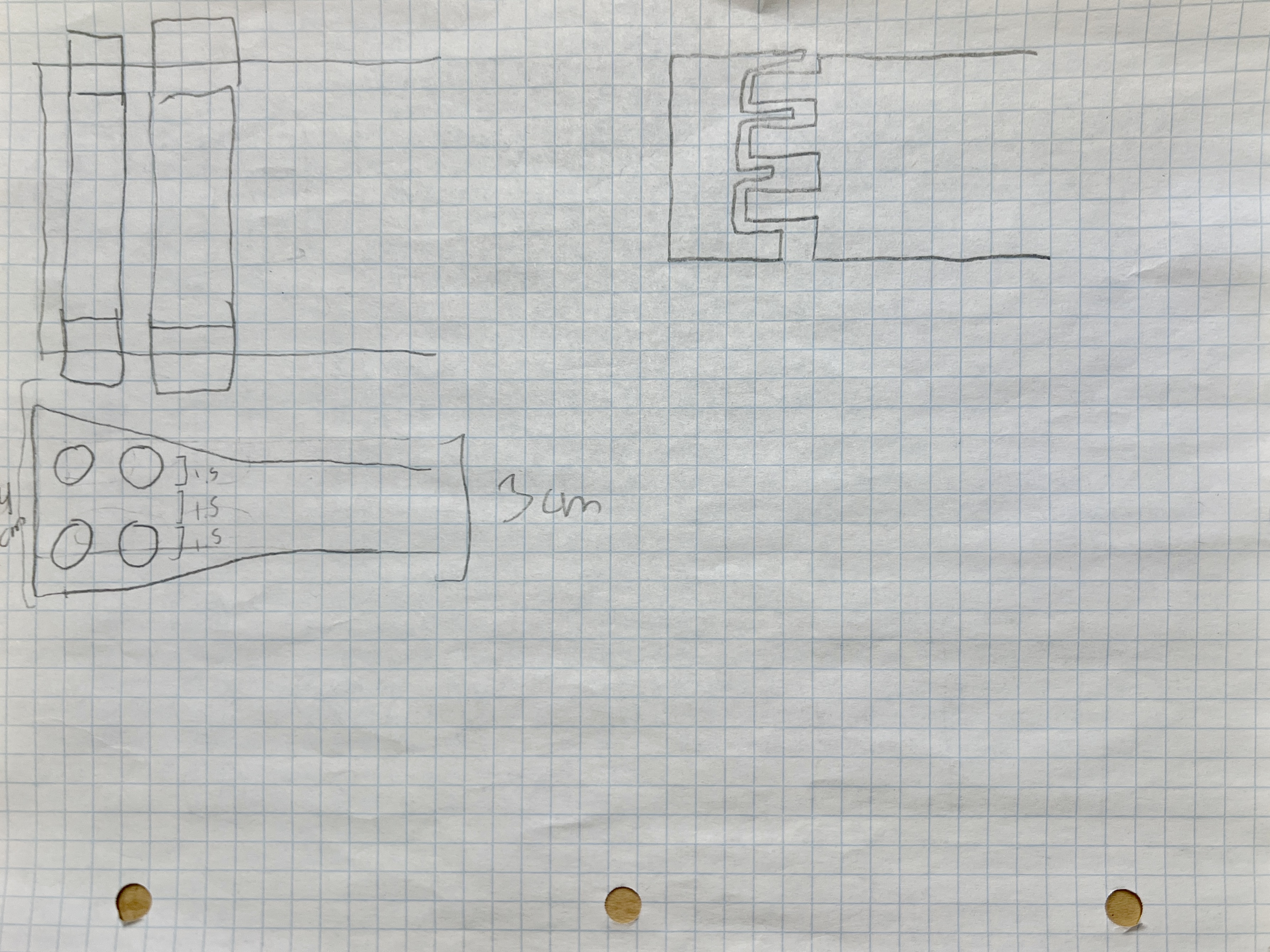
Top left: I have honestly no idea what that was supposed to be.
Top right: A hypothetical joint for joining 2 parts, allowing one to make a longer arm on a standard 25x25cm printer bed.
Bottom left: Another idea for a magnet holder, this time on its side with 4 holes. This was ditched because The magnet’s couldn’t be held sideways. Although this would make it harder for them to get pushed or pulled out by magnetic force, they had to be vertical so their fields would be in line with that of the electromagnet. 4 also doesn’t allow an always even distribution of magnets around the center regardless of count; 5 holes in a cross does.
Page 2!
Page 2a
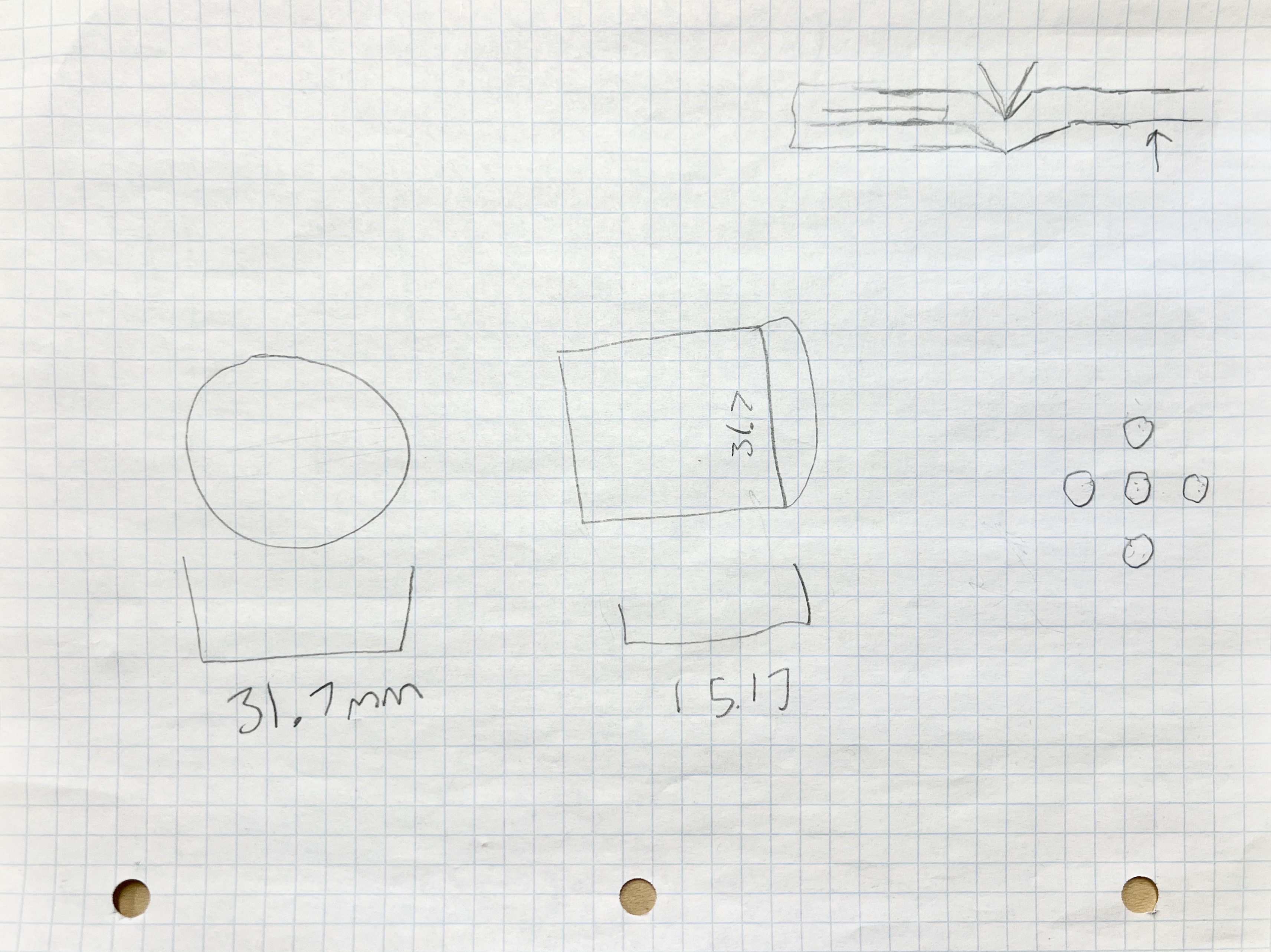
Top right: Another doomed fulcrum doodle.
Center: The dimensions (in millimeters) of the (1.25 inch) weights that we’d be using. Which are denoted in grams. Hm.
Right: A doodle of the 5-point array for magnet gripholdery.
Page 2b
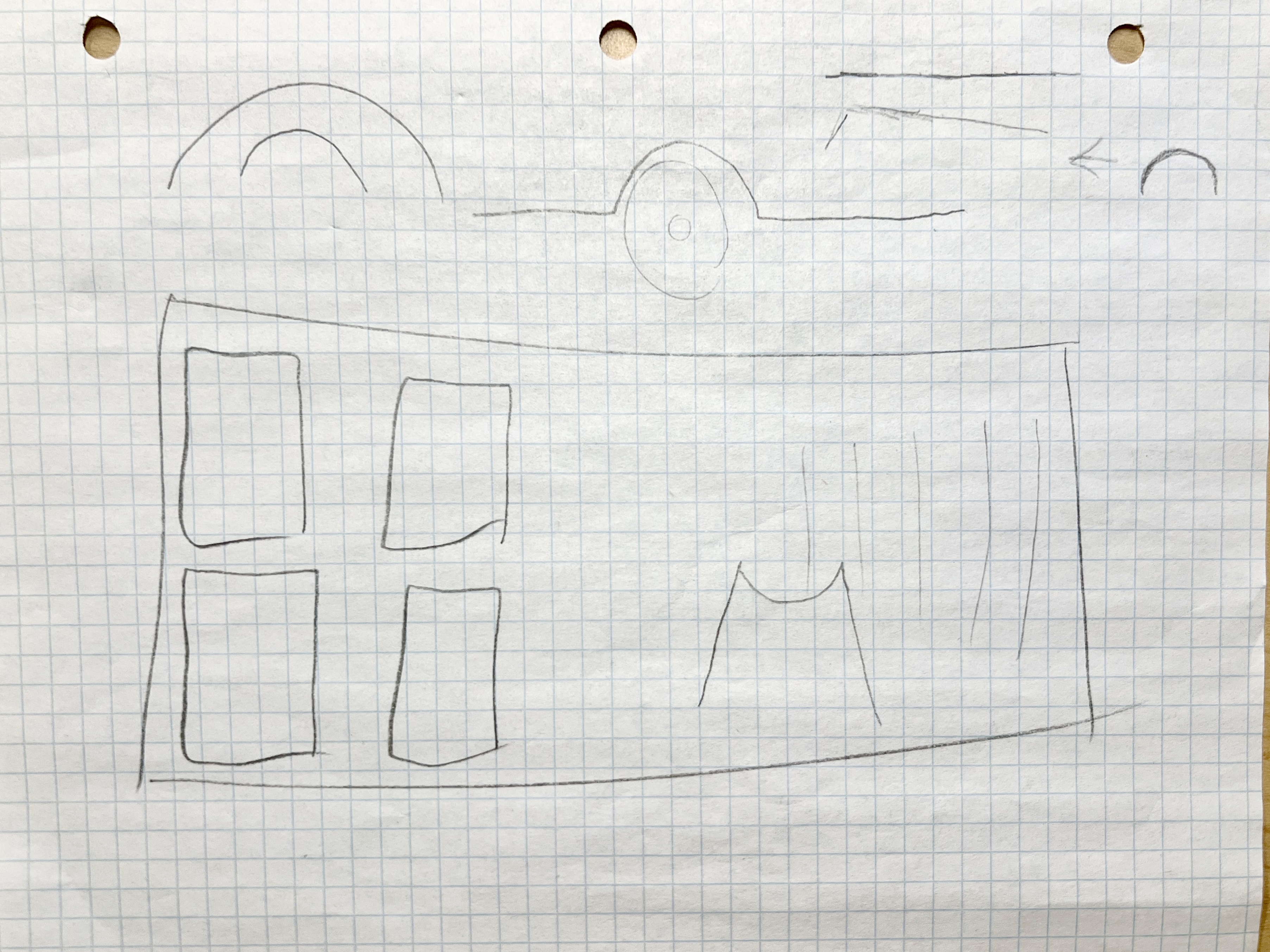
Top: A weird concentric-circle fulcrum, I think?
Center: an idea for an array of troughs to hold the cylindrical weights. This got axed.
Page 3!
Page 3a
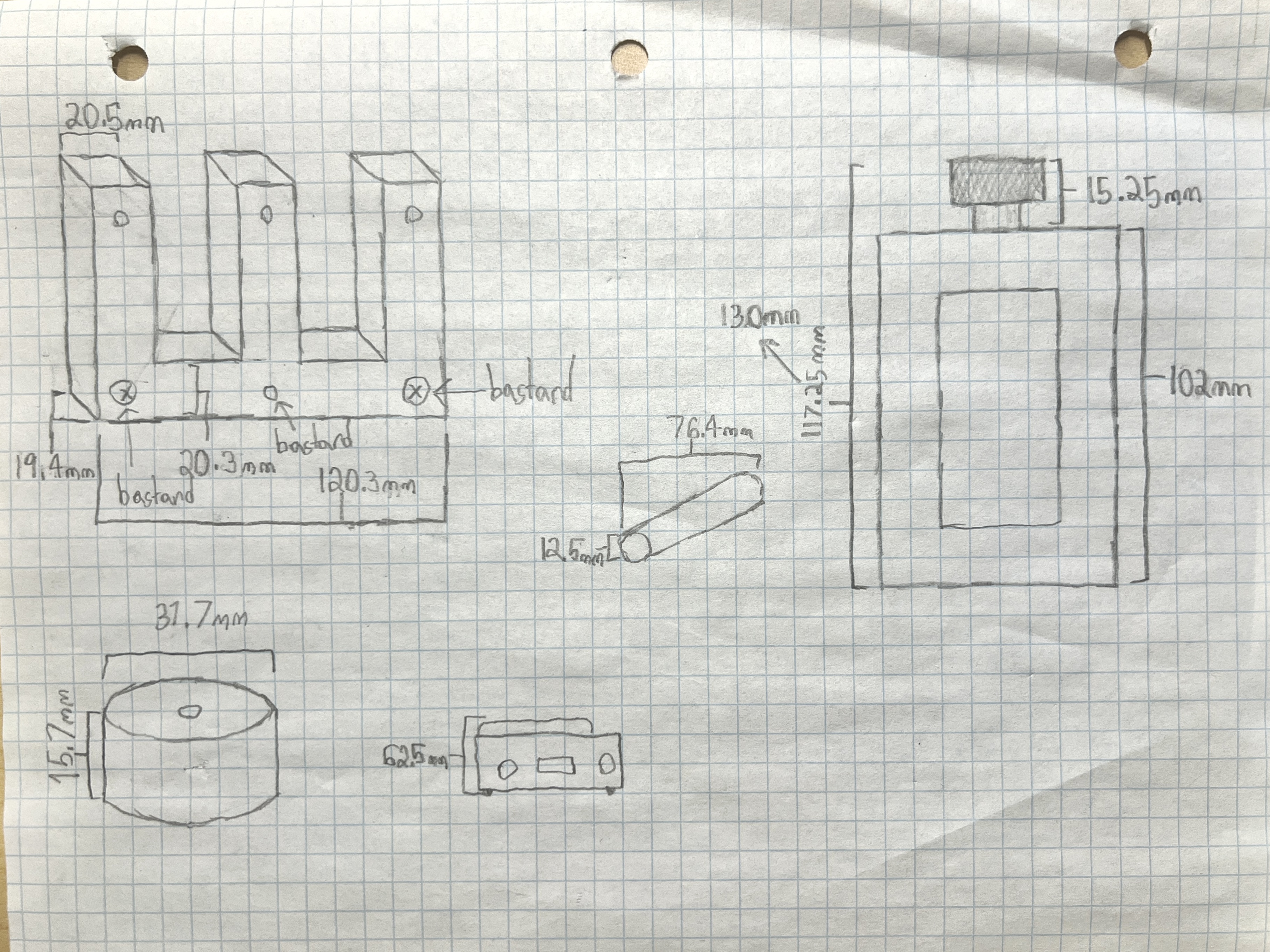
Top-left: The dimensions for one of 3 iron cores that came with the electromagnet kit. This core didn’t end up getting used, as it was too big, lacked a second piece to form a closed iron loop, and due to the low height of the scale - and thus the arm, gat axed because it would have to be suspended over the magnetic side of the arm on a ring stand - which it was too heavy for.
Center: The dimensions of one of the half-inch magnets outlined for use in the project.
Right: The dimensions for the iron core I ended up using, which was able to screw shut on a coil - both allowing a closed magnetic loop and the ability to clamp on something to hold it on a ring stand.
Bottom left: Dimensions for the 1 ¼ inch 100g weights, again.
Bottom center: The height of the electronic scale the lab would use.
Page 3b
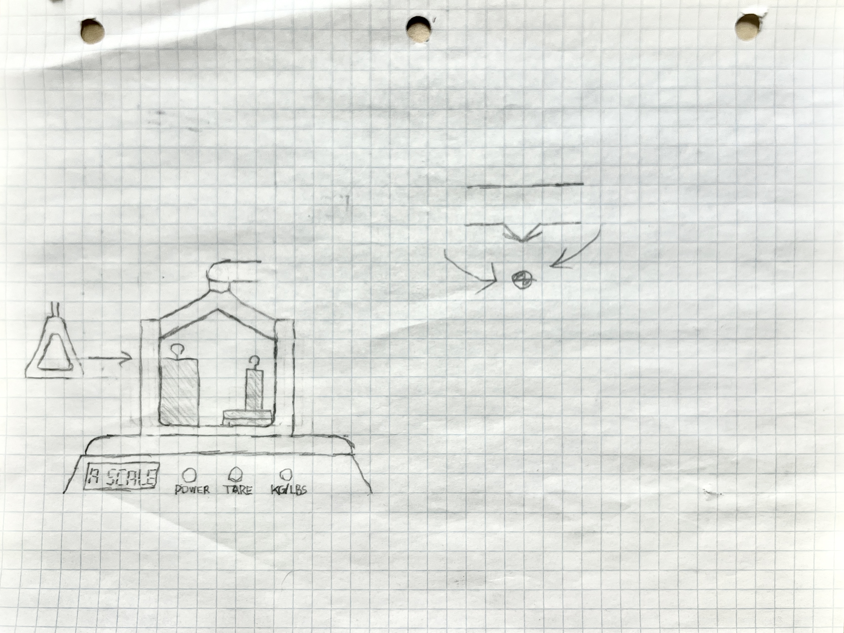
Left: An alternate idea to the trough, where weights of all sorts could instead be held on a pivoting ferris wheel-style carriage. This was axed for being too big, too complex, and really really really dumb and bad and hard to do.
Right: The doomed fulcrum yet again.
Page 4!
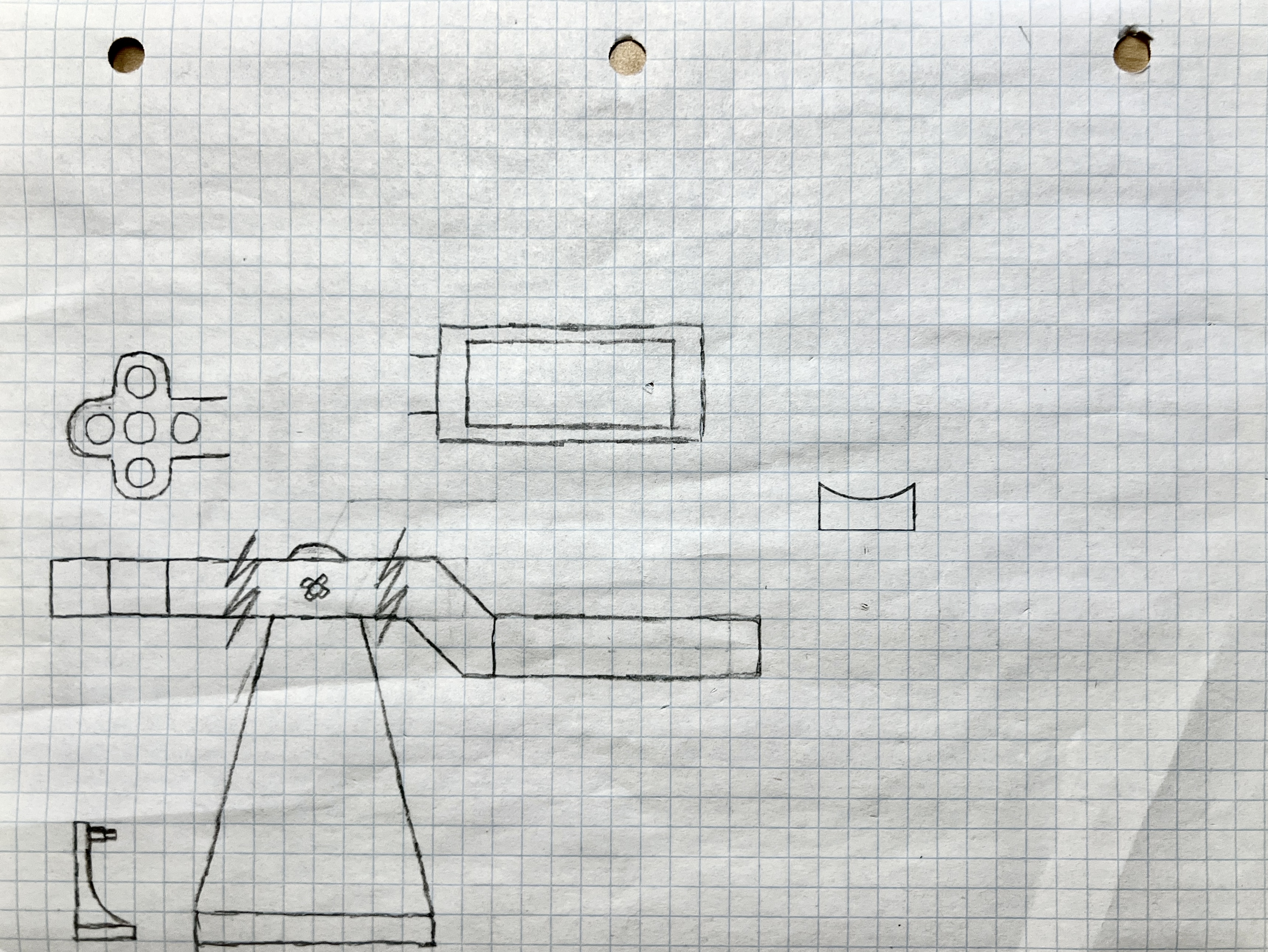
Center left: A top-down sketch of the final “paw” magnet hole arrangement, that allows you to center the mass of 1 to 5 magnets.
Center: A top-down sketch of the final “trough” receptacle for holding the zeroing weights.
Right: A side view of the trough.
Bottom: The final sketch of all 3 arm parts and the stand. There was originally a peg and crosshole arrangement for the axle, but this would be later replaced in the design as just a circular hole and a screw; the crosshole was elaborate overkill and didn’t really have a way to affix the arm and keep it from falling off.
Page 5!
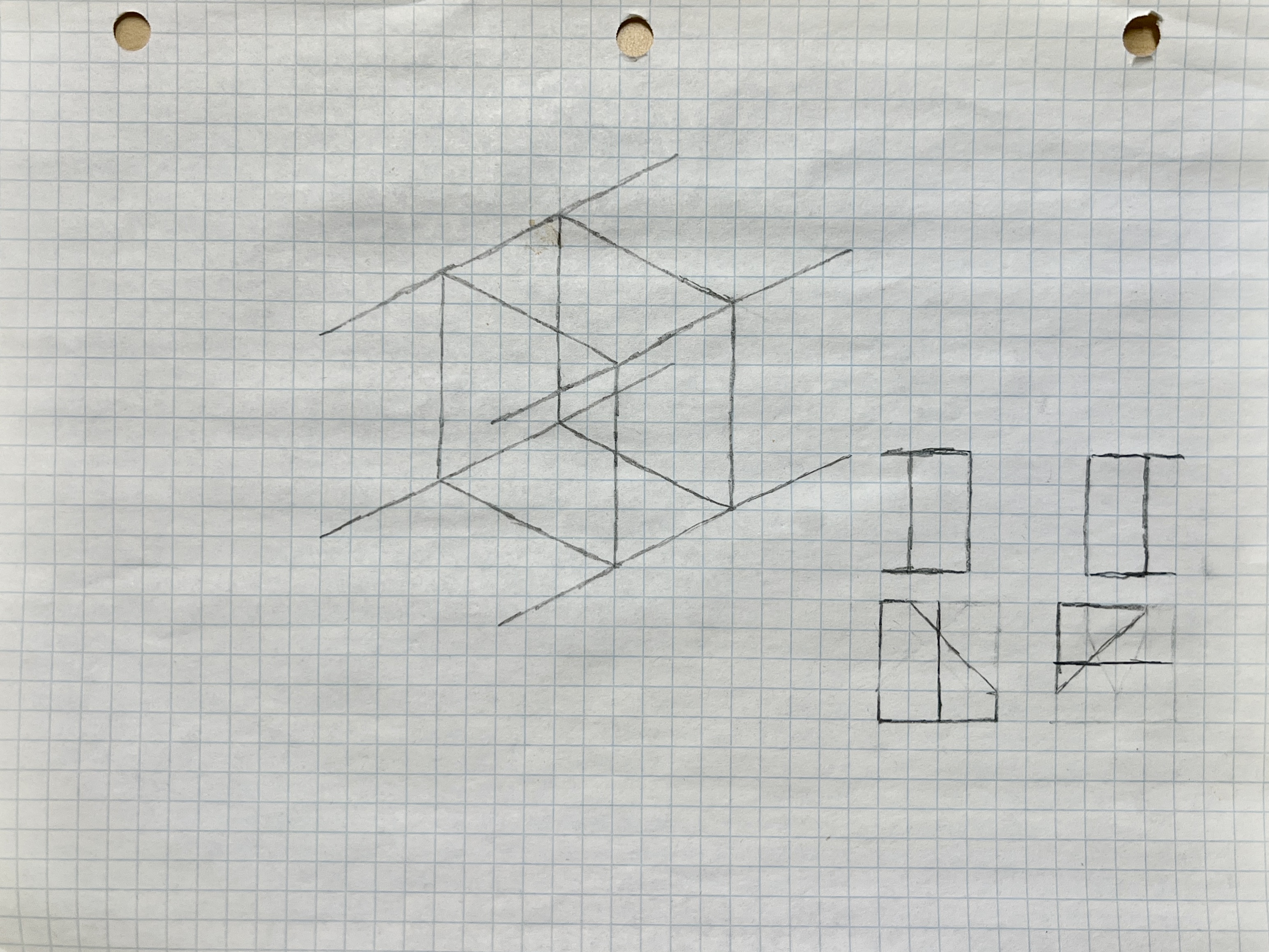
Center: a sketch of the 1-cm overlap between 2 arms where they’d be joined. This was later extended to 2cm of overlap.
Right: Ideas for overlapping segments to join the arm segments. I struggled with this, as the arms had to be 3d-printed 90 degrees relative to each other in order to print the parts cleanly without supports. The overlapping segments would also have to print without supports, and still line up after rotated 90 degrees to align the arms. I put way too much thought into what shape could do this securely, until I realized that just 2 rectangles with one on its side and one on its bottom would do just fine. A bolt was also added going through the parts to fix them together.
Page 6!
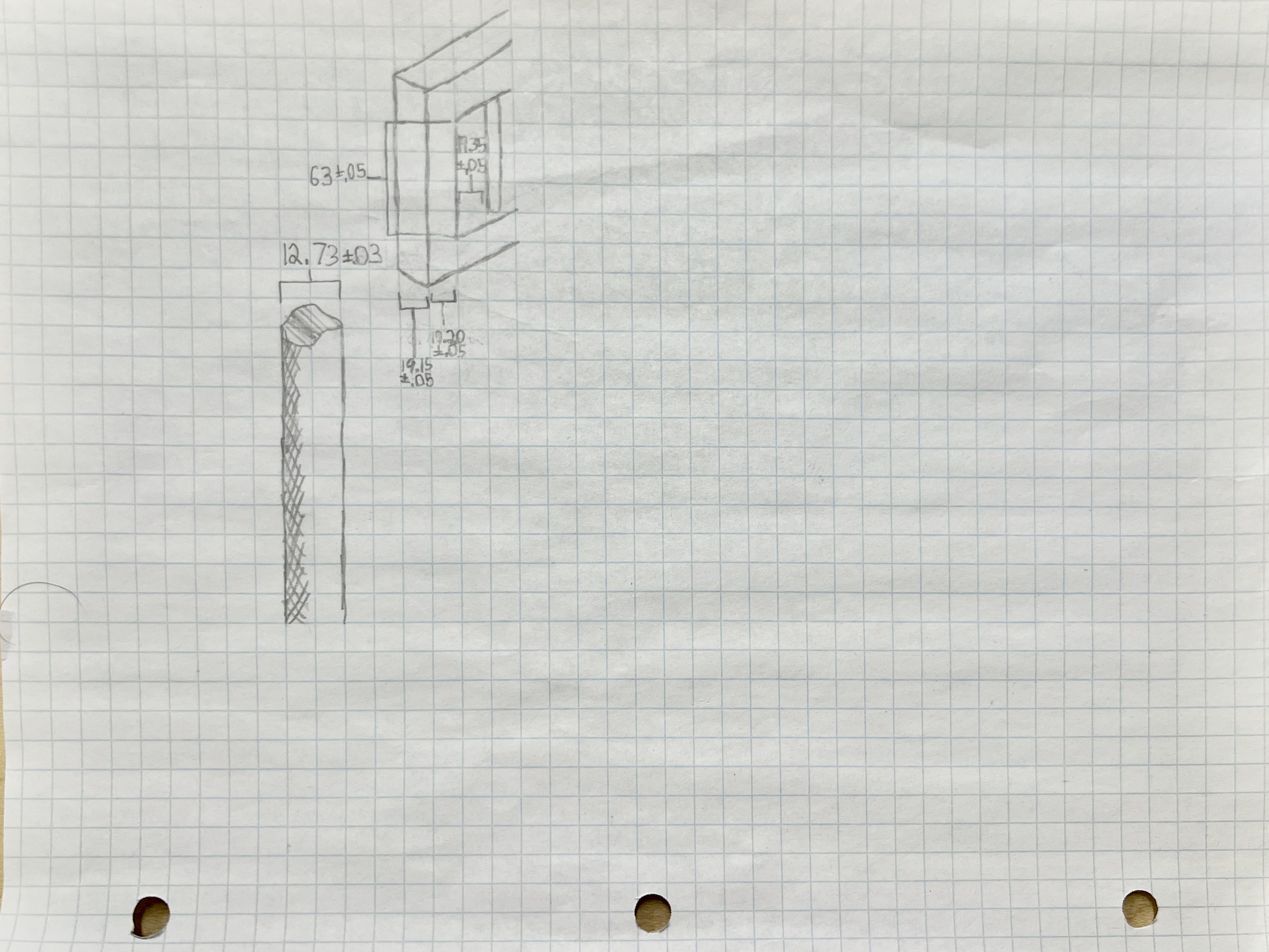
Top: Dimensions of the iron core… again. This time they’re for making the electromagnet ring stand holder.
Left center: Circumference of the half-inch ring stand… in millimeters.
Ok so let’s do the development of the arm first.
The first iteration of the arm had a couple notable details.
- Each segment was rolled 90 degrees to avoid sketchy print layers and supports
- Chamfers were put on the paw holes to allow easier magnet insertion
- The axle hole was changed to a smooth bore for an M4 bolt
- Re: The rectangular 2cm overlaps from sketch page 5
- M3 screw holes to fix each arm part together
- A backing at the end of the trough to keep the weights from falling off
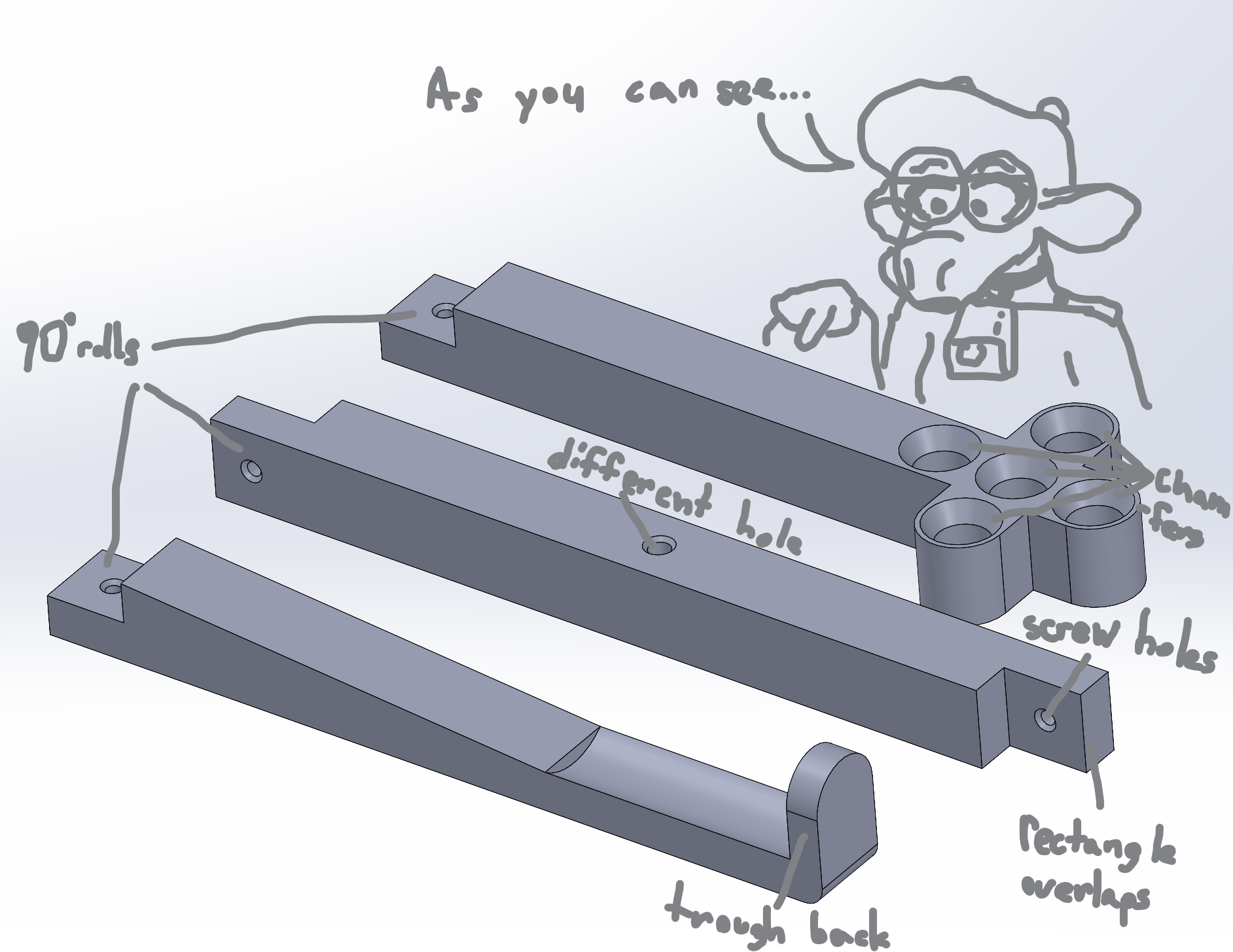
Moo o3o
There’s a few things wrong though; first, the holes are too small. The magnet measured was actually slightly defective, and the holes were widened to accept thicker magnets. Second, the magnet arm was lengthened so the center of its force and that of the weights’ would be equally far from the fulcrum - to avoid unwanted mechanical advantage.
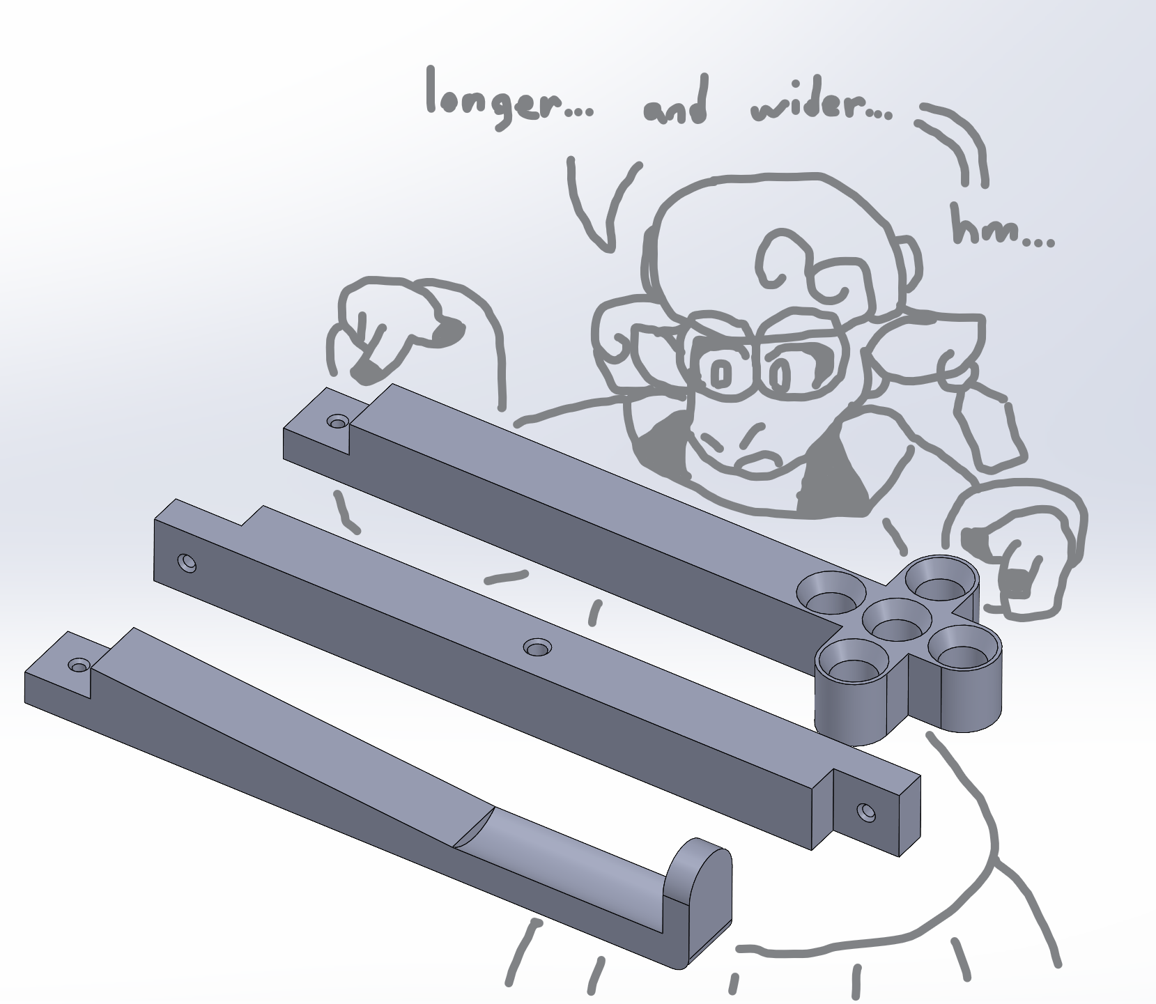
Ba-a-a-aa -w-
For the arm stand, I started with something like this. It was easy enough to make the shape, but then I needed to affix the seesaw arm somehow. I had to decide between printing a pole or making a hole. The 0.1b version has neither.
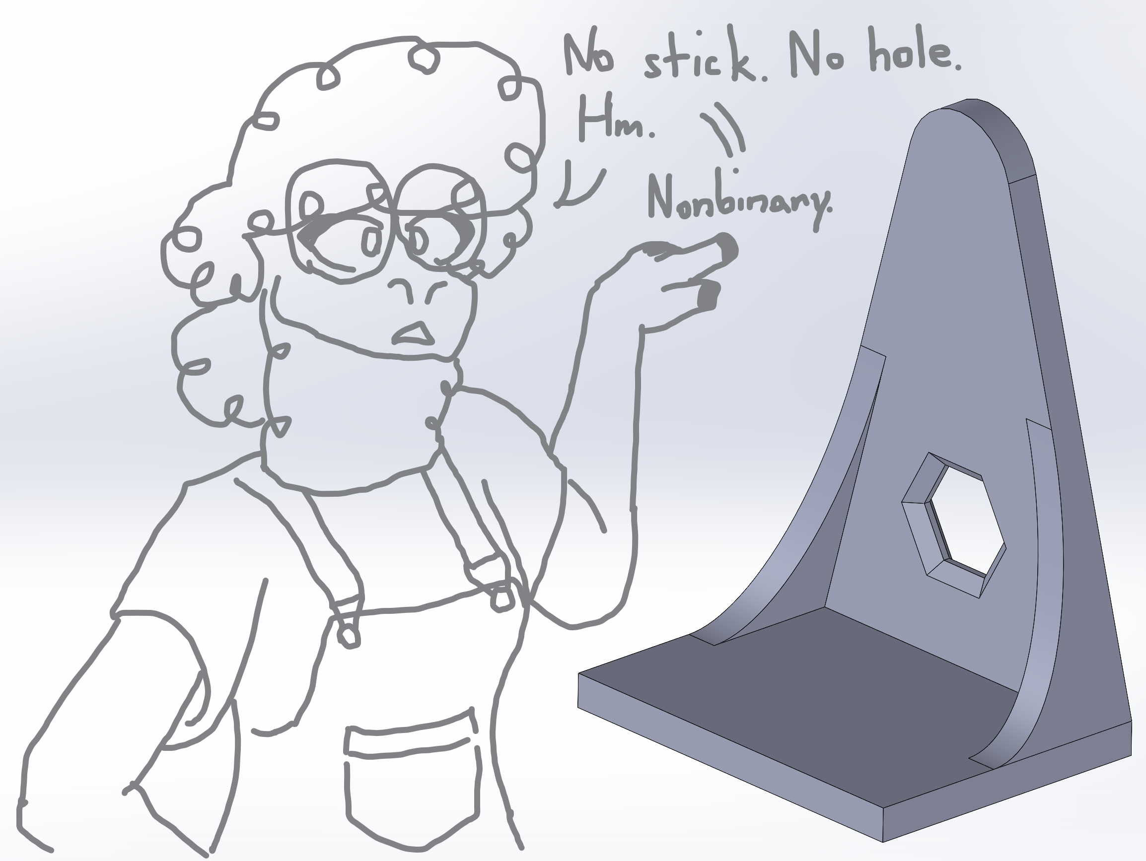
What noise do llamas make? They spit a lot… hm… hawk tuah? No, no, I have to reject that on principle.
But first, Aesthetics™!
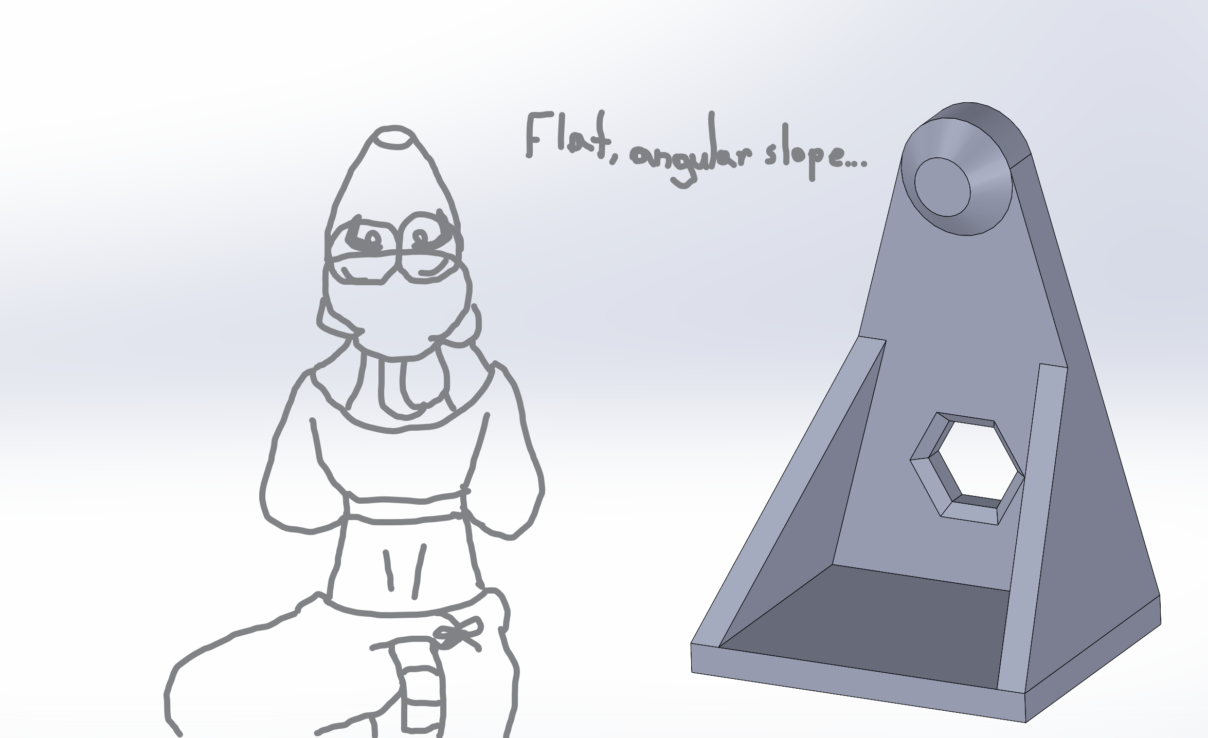
squeak! :>
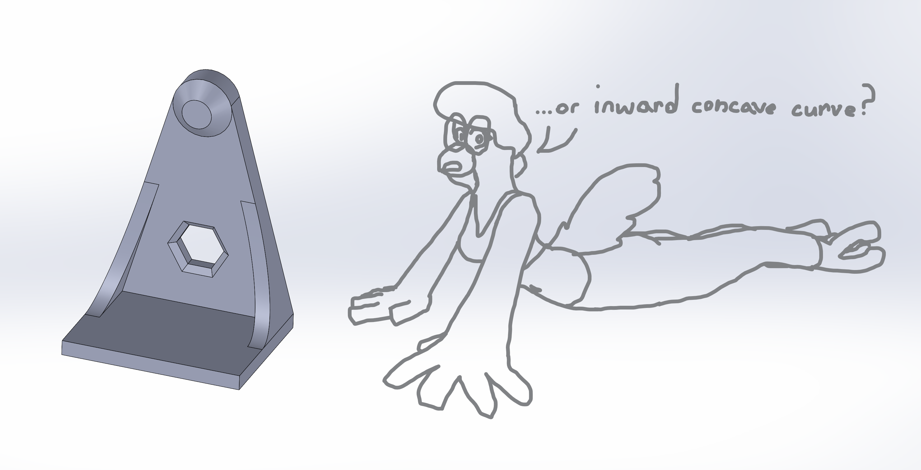
I’d cluck, but having grown up with chickens I happen to know they actually crow and croon. It's more like a “ruuuuuuuur-ruuuuur-ruurrrr-uurr-uurr.”
I went with the curve.

Squawk beats squeak :O
Now, Back to the hole thing. Yeah, I went with a hole since I was already using hardware, and an M4 bolt and nuts just seemed easier and sturdier. I also added a chamfer to the hole to reduce physical contact - and thus friction - with the arm. The protrusion it goes through, while partly doing the same, also offsets the arm to center it over the stand’s footprint.
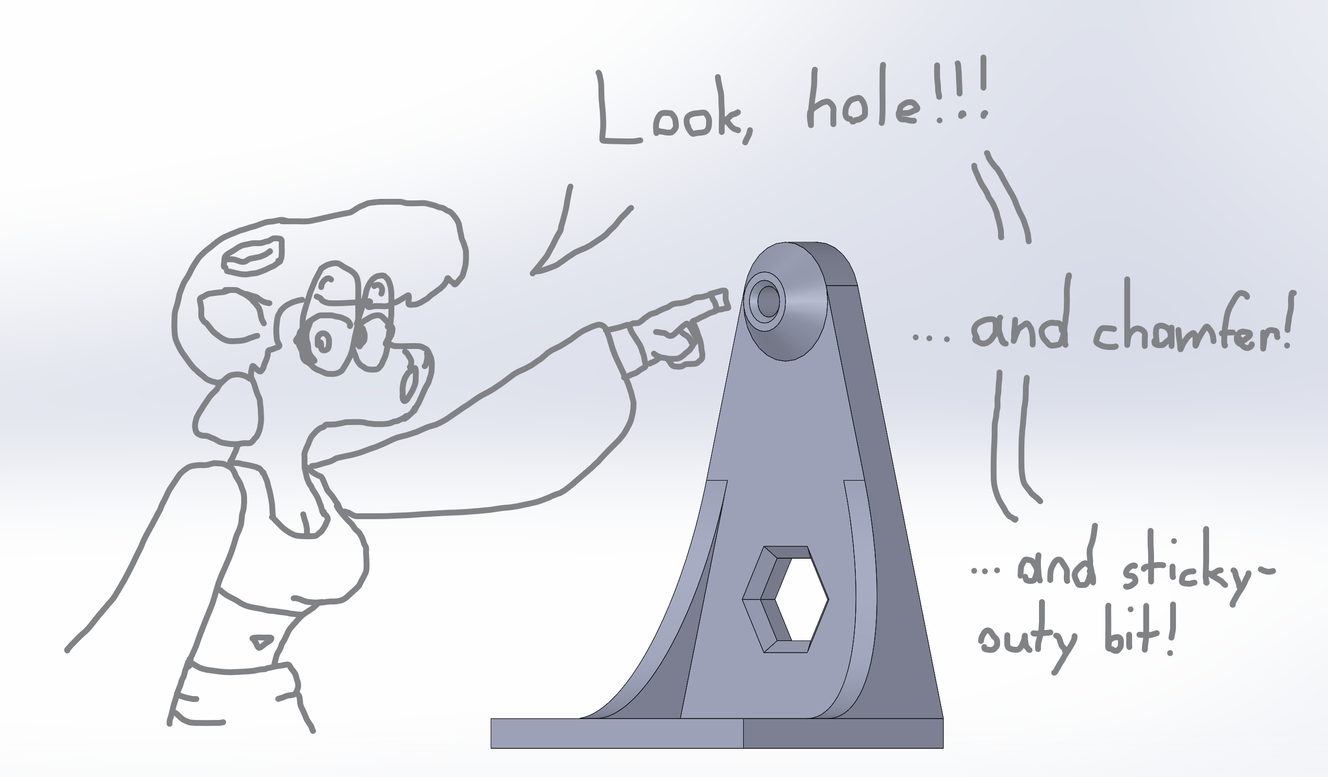
bleat! :3
Lastly, the magnet holder! It was kinda simple actually, pretty much just banged it out in one. It’s got a collar to hold the magnet’s core, a sturdy arm, two ring clamps to attach to a ring stand, (again using M4 hardware,) and – of course – hexagons. :3
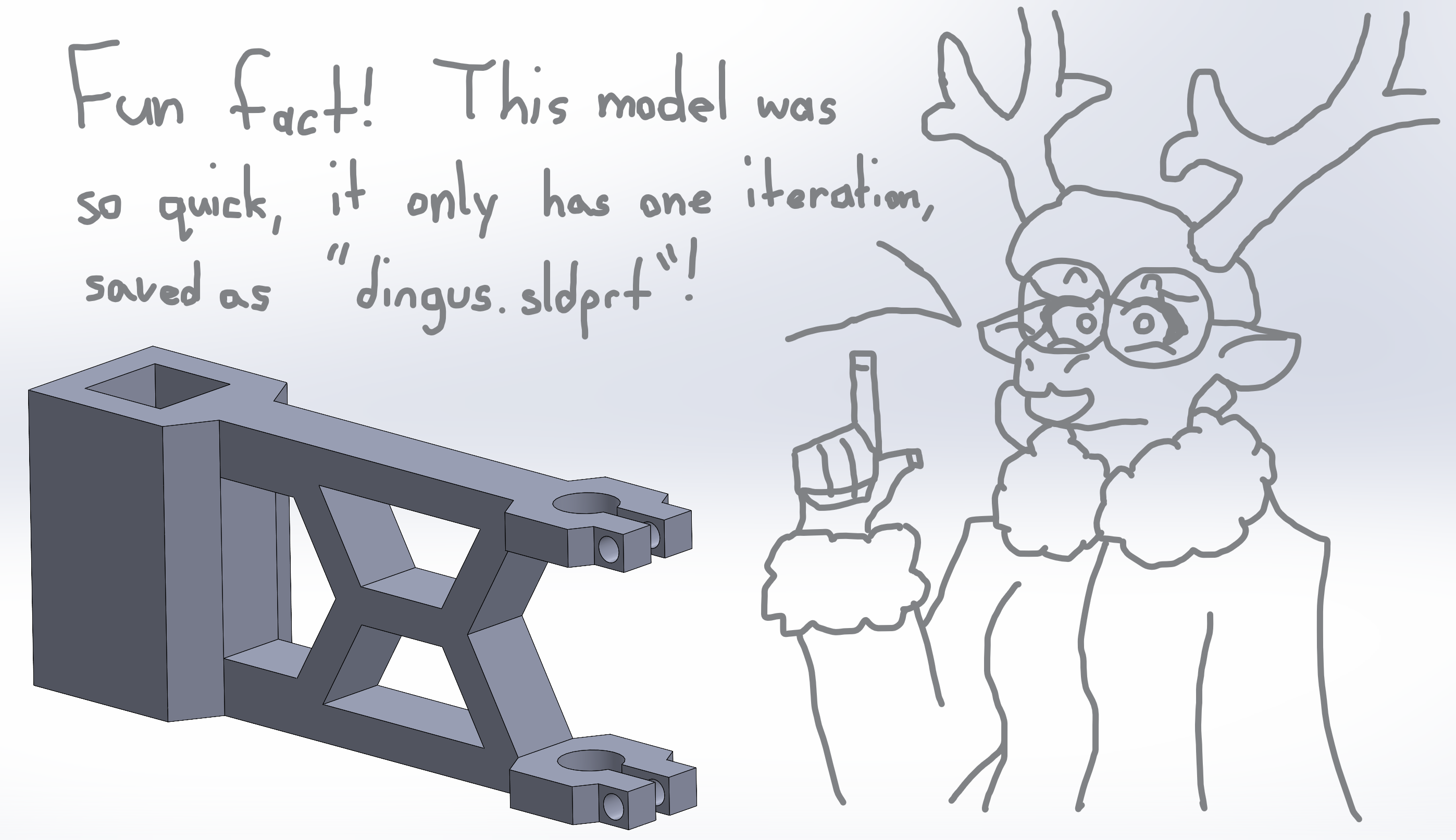
honk!!! yea, turns out reindeer honk! :D