
12-Bay ATX NAS case
Obliczymy ostateczną cenę na podstawie wybranego pliku. Sprawdzisz ją i zaakceptujesz przed płatnością.
Zapisane na tym urządzeniu.

Up to 12x 3.5 inch hard drives, ATX PSU, 245MM GPU, Air cooler up to 160mm, Easy cable management.
- Ocena
- 5 / 5
- Polubienia
- 706
- Wydruki
- 19
- Wyświetlenia
- 31 427
- Oceny
- 19
Aktualizacja u źródła:
Informacje o modelu
- Źródło
- Printables
- Kategoria
- Computers
- Licencja
- Standard Digital File License
Now available with front air intake as well!
The file called FRONT_AIR_INTAKE_VERSION_drive_bay_1_2_3_4 can be printed instead of the original drivebay. (See pictures for example)
This project is designed specifically to be compatible with even 180 x 180 mm printbeds, so you'll be able to make this project even if you have a Original Prusa MINI+ or anything larger.

IMPORTANT: Before printing all the parts, please print the tolerance test STL to ensure the joint tolerances fit. More information can be found further down on this page. |
|---|
Case dimensions:
The overall case size including the feet is: 430 x 430 x 200mm.
Estimated filament usage:
Based on the exact setup shown you'll need about:
- 2.5 to 3.0 kg of black PETG or similar filament.
- 1.5 to 2.0 kg of grey PETG/PLA or similar filament.
Combined total filament: approx. 4.5 to 5.0 kg.
(The estimate above WILL vary slightly for everyone.)
As an Amazon Associate I earn from qualifying purchases. All product links below are Amazon affiliate links.
Parts compatibility:
ATX, mATX and ITX motherboards.
Up to 12x 3.5" Hard drives.
ATX or SFX / SFX-L power supplies (all depths)
4x 120mm computer fans, 15 to 25mm thick.
Graphics cards or other PCIe cards up to 245 millimeters long.
Adapter for 2.5" drives added 24MAY25.
Practical case features:
Actively cooled drive bays. (Air intake passing through drive bays)
Self-latching drive mounts for quick and easy drive swaps.
Easy access to all PCIe slots except the very bottom one. (Update may come)
Front-to-back airflow passing the CPU cooler.
Magnetic removable side panel for easy access.
About the design:
Easy to build with almost all parts numbered for easy part management.
Sturdy design with interlocking parts combining sliding joints and screws for maximum stiffness.
All parts print with zero support material.
Parts required to build the case: (Not so specific, will be updated soon)
M3x10mm screws (Get a pack of 100, It'll be enough)
M3xOD4.6x5.7mm threaded brass inserts (Get the 100 pack here too!)
8x3mm Neodymium magnets (A pack of 30 or more should be good)
At least 4x #6-32 HDD screws per hard drive. 12 drives = 48 screws.
Printing instructions and recommended settings:
The most important thing to keep in mind is that panel number 20, 21 and 22 are designed as solid objects, but require special slicer settings. Most of the other parts can be printed with “normal” settings.
Joining pieces 12, 13, 33 and 35 is highly recommended to be printed with denser infill and more walls to ensure part stiffness.
Layer height: (and tolerance testing)
Recommended nozzle: 0.4 mm (Many users report 0.6mm nozzles works fine too)
Since most parts have a fixed tolerance of -0.1mm the overall tightness of the sliding joints may vary a lot from printer to printer and filament to filament due to many factors such as print temperature and layer height. If the joints feel too tight, try a smaller layer height, and if the joints feel too loose, try a bigger layer height.
If the step above does not give you the result you’re after. Try increasing or decreasing the flowrate slightly to extrude more or less plastic per layer. This will affect the tightness.

Small layer height = usually more precise parts and less friction.

Tall layer height = more layer line texture and more friction.
Are you not sure how well your printer handles the tight tolerances? The file called “TOLERANCE_TEST” allows you to test different layer heights and print settings before starting the main prints to minimize the risk of wasted prints.

Recommended general settings for most parts:
Top and bottom layers: 3-5 layers
Walls/Perimeters: 4-5 layers (or 2mm thickness)
Infill type: Honeycomb, Cubic, Gyroid, Grid or similar.
Infill percentage: 15-20%.
See settings above this section about layer height.
The special settings required for panel 20, 21 and 22: (Critical for airflow!)
Top layers: ZERO
Bottom layers: ZERO
Walls/Perimeters: 5 (or 2mm thickness)
Infill percentage: 20%
Infill type: Honeycomb (IMPORTANT)
--------------------------------------------------
Do you have trust issues with your printer on long prints?
Try splitting the biggest STLs into single objects to minimize risk in case of failed prints.
Many of the STLs are pre-bundled together, if you need to print individual parts, most slicers will allow you to split the bundled parts into individual objects by right clicking on it while on the build plate. (See example below)


MAKERUNIT's Discord server is now public:
Do you have questions about this project or want to discuss this, or other projects with other makers? The MAKERUNIT Discord server is now open for everyone. Join by clicking here!
Step-by-step building instructions:
This step-by-step instruction will deviate slightly from the order shown in the video, but the result will be the same.
Start by laying out panel 15, 14, 12, 19, 16, 13, 18 and 17 in front of you. Use the picture below as a reference on how to connect them together. Add M3 threaded inserts into all locations marked with orange circles. The standard screw for this whole build is M3 x 10mm.
As the sliding parts WILL lock in place and be difficult to take apart again it's important that we first slide in place the two upper panels (14 and 15), then the two lower panels (17 and 18), and THEN the two middle panels 16 and 19.
Now let's slide together the drive bay. The drive bay consists of part 1, 2, 3 and 4. These have built in tracks in all corners and middle joints and we want to slide them together. Add threaded inserts to all locations marked with orange circles.

Add panel 20, 21 and 22 to the backside of the drive bay using M3 screws. Also secure part number 7 (the foot) to the underside of the drive bay.
Remember that these panels must be printed with out top or bottom layers and honeycomb infill. See the recommended settings for these panels before the start of this instruction.
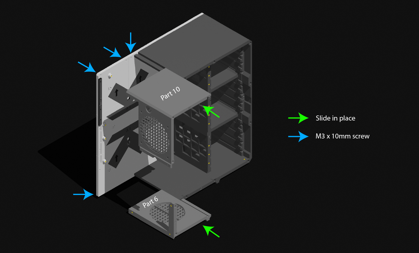
Add M3 threaded inserts to part number 5, 6, 10 and 11.

Slide in place panel 11 in the slot in the top left corner of the drive bay, followed by panel 5 into the lower left corner of the drive bay.

Secure the motherboard back panel to the drive bay, panel 11, and panel 5 from the backside using M3 screws.

Flip the whole assembly over and slide panel 6 into the track in panel 5, as well as panel 10 into the track in panel 11.
Add M3 threaded inserts to part number 8 and 9. The power supply bracket (number 8) comes in two different options; ATX or SFX, but both use the same threaded inserts.

Screw in place panel 8 (PSU bracket) and panel 9 (PCIe slot mount) using M3 screws following the picture below.

The main chassis is now done with the exception of the magnets which we will add at the end. Here we can see how to install our fan brackets; these simply slide into place without any hardware except for mounting the fans to the bracket.

Outside of the fan brackets we can screw into place the cable management brackets using M3 screws. These have a dual purpose by also locking in place the fan mounts.

We can now put together our magnetic side panel, this is summarized into one single picture as this felt like it made sense. Let me know in the comments if this explaination is too complicated.
FYI: The middle locking part 34 is found in the same STL file as part 23.
8x3mm Neodymium magnets can then be added to all the 8mm holes around the edge of the chassis, as well as around the edge of the magnetic side panel. Just make sure that the magnets are pushed in the correct way on both sides so they attract each other. By pushing in all magnets from the same side of the magnet stack, it's very easy to simply flip the stack 180 degrees before pushing it into the opposing side, this ensures correct polarity. However, check the YouTube video for a better visual explanation.
Secure in place the lower front foot (part 7) right underneath the drivebay using two screws.

To mount the sliding mount to each hard drive we'll need a minimum of 4x #6-32 HDD screws for each pair of gliders. The glider track with the built in spring and latching mount should be mounted on the drive's right side.
Now it's just a matter of throwing in some parts and we're good to go with our new NAS.
This written instruction describes the building process to my best ability. More information may be added gradually as requests or needs come up.
Don't hesitate to ask any questions you may have.
-makerunit

UPDATE LOG:
09MAY2025: Added a new file “5_6_7_10_11_main_body_parts_v1.2” due to in v1.1 there are two parts accidentally placed too close causing the parts to merge during printing. This concerns part 6 and part 10, and need to be carefully cut apart a few millimeters. Luckily this little defect is not visible from the outside of the case as both surfaces affected are facing into the case. The .step file is not updated as it doesn't directly affect the model, only how the parts were arranged during STL export. Problem solved.
24MAY25: Added adapter for 2.5 inch SSD. This mount bolts directly to the sliding brackets using M3 screws. The little arrow indicates which side to mount drive and direction of it's connectors.

11JUN25: Updated part 9 and 10 with one extra threaded insert hole at the top of the PCIe slot cover (to support 1-slot cards in the upper slot). Part 9 also now has some extra space at the bottom allowing you to utilize the bottom PCIe slot (slightly angled upwards, but works).

30SEP25: Added front air-intake version of the drive bay part 1, 2, 3 and 4.

18OCT25 (1):
Added updated file “FRONT_AIR_INTAKE_VERSION_drive_bay_1_2_3_4_v1.6” due to minor misalignment in the v1.5 STL causing one of the four sections to be printed in mid air for the first layer.
Before vs. after fix:


18OCT25 (2): “AS_SHOWN_VERSION_1_2_3_4_drive_bay_modules_v1.6” is now updated to repair a non-critical bug where some holes were printed in mid-air resulting in stringing issues for some users. This issue was fixed for both drive bay versions.