
OG Star Tracker V2 - Illuminated Polar Scope Mount
Obliczymy ostateczną cenę na podstawie wybranego pliku. Sprawdzisz ją i zaakceptujesz przed płatnością.
Zapisane na tym urządzeniu.
Polar scope LED lights with switch and potentiometer powered by CR2032 battery.
- Ocena
- 0 / 5
- Polubienia
- 9
- Pobrania
- 63
- Wydruki
- 0
- Wyświetlenia
- 588
- Oceny
- 0
Aktualizacja u źródła:
Informacje o modelu
- Źródło
- Printables
- Kategoria
- Physics & Astronomy
- Licencja
- Creative Commons — Attribution — Noncommercial — Share Alike
This is a modified polar mount for the OG Star Tracker V2 that adds some LEDs. Due to the small space constraints, it isn't the most straightforward build, but it does work pretty well once assembled.
I used the switch and potentiometer I had on hand, which probably made it harder than just buying a potentiometer with a switch. I will include the STEP file so it should be pretty easy to modify the electronics compartment to a a switched potentiometer if desired.
IMPORTANT NOTE:
This will only work with my single piece gearbox mod and the upcoming revision of the OG tracker, which will also combine the gearbox 1-2 pieces into a single piece.
Changelog:
- 2025-08-10
- added a wiring diagram.
- 2025-06-05
- Removed the beta pot only file. I ordered some of the pot/switch combos and they don't work. I'll play around and see if I can make it work later.
- 2025-05-18
- Realized that the scope only works with single piece gearbox 1-2 due to interference, so noted that in the description.
- 2025-05-12
- updated the[Scope Mount - Body - Pot and Switch - v1.1]. I had the “6” upside down. whoops :).
- added a new knob because the stock one interferes slightly.
- added BETA [Scope Mount - Body - Pot Only] with only a single hole to fit a switched potentiometer.
- I haven't printed this because I don't have a need, so not sure if the pot will go in without using the glue in Potentiometer Hole Cover.
- Added STEP file
BOM:
- (1) - Polar Scope of this style
- (2) - 3mm LEDs
- (2 ft) - >24 gauge wire.
- the thinner you have, the easier it will be. I used 26g.
- the strands from an ethernet cable will probably work well
- (1 ft) - 20-22g wire.
- 20g will work if you have FEP or PTFE wire.
- Can also use the thin gauge wire and just double/triple up the exposed wire ends.
- This is used to make the contacts to the 2032 battery.
- (1) - 10 x 15mm mini rocker switch
- (1) - WH148 5k ohm potentiometer
- https://www.aliexpress.us/item/2251832721838471.html
- Even lower than 5k is probably better, but all I see is 5k.
- Any potentiometer that attaches with a nut will probably work as long as it is smaller than the WH148, which is actually kind of big.
- (1) - 2032 battery (3v)
- (1) - 4.2mm brass heatset (from Star Tracker BOM)
- Superglue
Printing:
- 0.2mm layer height
- Use the provided print orientation
- Supports not required, but supporting at one spot will make the 2032 slot cleaner (see pic)

Assembly:
- There are three small holes where wires pass through. Two come from the top where the LEDs mount, and one comes through from the 2032 slot (light blue wire). You will need to punch through these holes with a small Allen wrench or tweezers.
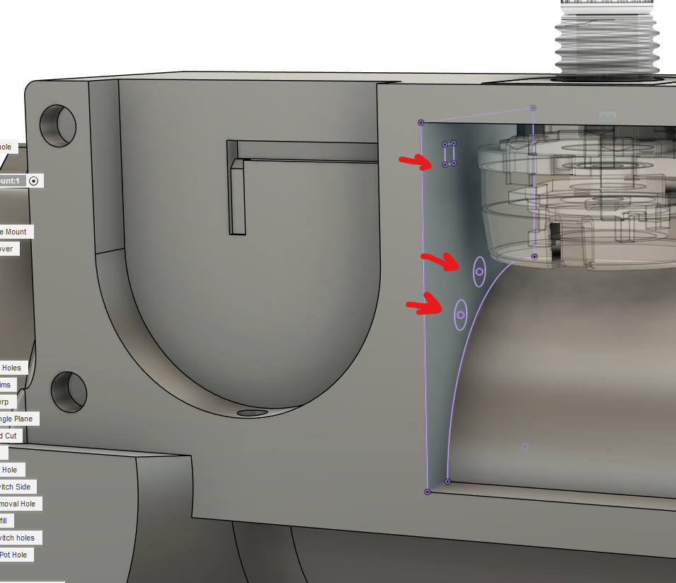
- Using the 20-22 gauge wire, create the contacts for both sides of the 2032 slot (light blue wire in the pic below). There's one in the main mount and one in the side cover.
- Fit the wire to the depression. Add solder to the exposed end of the wire to keep it from fraying and so that it sits just proud of the surface.
- Add a dab of glue to keep the wires in the channels

- Using the thin gauge wire, assemble the top LEDs.
- Remember the longer leg of the LED is the (+) leg.
- Wire the LEDs in parallel.
- After testing the LEDs, glue the cap to the mount.
 solder two pairs to one of the LEDs |  Pass a red and black through the holes down to the compartment with the potentiometer. Pass the other pair of wires under the bridge and around to the other LED location. |
 Solder in the second LED. There's enough space to fold the wire a little. |  |
 Glue the cap on after testing the LEDs. |  Wiring Diagram |
- Bend the contacts of the potentiometer straight down
- Bend the contacts of the switch so the point towards the LEDs
- Complete the wiring in the main compartment where the potentiometer and switch are. This wiring assumes that the (+) terminal is going to be on the side away from the side cover.
- Run the wire from the 2032 compartment on the main mount to the middle pole of the potentiometer.
- Then, wire from the right contact of the potentiometer to one leg of the switch (make sure the wire goes through the switch mount hole).
- Wire from the other leg of the switch to the (+) wire going to the LEDs
- Pop the switch into the mount hole.
- Insert the potentiometer up into main mount and turn it so the contacts face to the right. Put the small cover piece over the potentiometer stem and glue it in place. Now secure the potentiometer with the nut.
- Solder the contact wire from the side cover to the (-) wire going to the LEDs.
- Test that the LEDs power on.
- Remove the 2032 battery and glue on the side cover. Make sure you get a good bond as this is what is holding the contacts to the battery.
- Sorry, I forgot to take a picture of the switch compartment before I glued the side cover on :(
- Note there is a small hole for an Allen wrench under the battery slot so you can eject the battery.