
Logitech G29 Shifter Adapter - Arduino Nano ESP32
Obliczymy ostateczną cenę na podstawie wybranego pliku. Sprawdzisz ją i zaakceptujesz przed płatnością.
Zapisane na tym urządzeniu.

This is a mod that makes the Logitech G29 a standalone shifter, no need to buy the required wheelbase.
- Ocena
- 0 / 5
- Polubienia
- 7
- Pobrania
- 16
- Wydruki
- 0
- Wyświetlenia
- 897
- Oceny
- 0
Aktualizacja u źródła:
Informacje o modelu
- Źródło
- Printables
- Kategoria
- Electronics
- Licencja
- Creative Commons — Attribution — Noncommercial — Share Alike
This is a modification to make the great gear shifter Logitech made to a standalone product. It's cheap and reliable, available to many and works great.
The concept:
There is one predominant way that has gained popularity. But there are some limitations to that. It doesn't work with Arduino Nano and some others. Since it's available to me I wanted to use Arduino Nano ESP32 because of its small size and the USB C connector.
This project requires you to cut the cable and solder directly to the Arduino. If you are not into that you can always follow this great tutorial made by Dave Madison, link below, it requires no soldering.
- https://www.partsnotincluded.com/how-to-build-a-diy-logitech-shifter-usb-adapter/
How this works:
The shifter uses two potentiometers to get the position of the shifter and one button for reverse. The Arduino interprets that to seven separate button presses.
----------------------------------------------------------------------------------------------------------------
Tools that are required:
Good small soldering iron like the Miniware TS100, small tweezers and side cutting pliers
----------------------------------------------------------------------------------------------------------------
Step 1: Flashing Circuitpython
Flash the Arduino with Circuitpython
- https://circuitpython.org/board/arduino_nano_esp32s3/
I recommend that you use the installer. This step can be tricky, you need to get the Arduino into boot loader mode.
To enter bootloader-mode, press the reset button, and then press it again once you see the RGB LED flashing. You'll know that you've successfully entered bootloader-mode if you see the green LED pulsing slowly.
https://docs.arduino.cc/tutorials/nano-esp32/cheat-sheet/
----------------------------------------------------------------------------------------------------------------
Trouble with flashing you Arduino Nano ESP32?
You might need to go a little bit different route than what is described above. Download the latest Circuitpython .BIN then go to https://espressif.github.io/esptool-js/ and use this tool to flash it.
Connect to it, then hit “Erase Flash”. When that is done refresh the page. Connect again, then select the .BIN file, change the flash address to 0x0 and press "program". You should see a some text appear stopping at “Hard resetting via RTS pin...”. When that is done you can press the reset button on the Arduino, you should see it open up the directory of a device called “CIRCUITPY”. Now you are ready for the next step.
----------------------------------------------------------------------------------------------------------------
Step 2: Setting up JoystickXL and files
Download JoystickXL's latest build.
https://github.com/fasteddy516/CircuitPython_JoystickXL/releases
Installation
- Download the latest release of JoystickXL that corresponds to the version of CircuitPython you’re running. (i.e.
joystick_xl_x.x.x_cp8for CircuitPython 8.x)- Extract the files from the downloaded .zip archive.
- Copy the
joystick_xlfolder to thelibfolder on your device’sCIRCUITPYdrive.
https://circuitpython-joystickxl.readthedocs.io/en/latest/start.html
This step is very important, at this point your Arduino should be showing up as CIRCUITPY drive. There you need to place place the contents of JoystickXL's.zip folder into the lib folder lib > joystick_xl. To make this work you need to add one more file into the lib folder. Make a text document (right click new > text document) and paste this:
class VirtualButton:
   def __init__(self):
       self._value = True
   @property
   def value(self):
       return not self._value  # Invert for HID (False = pressed)
   @value.setter
   def value(self, val):
       self._value = not val  # Store as inverted internally
Save it as virtual_button.py (not .txt). Use File > Save As, choose All Files under “Save as type”, and name it exactly: virtual_button.py.
----------------------------------------------------------------------------------------------------------------
Step 3: HID setup
We need to setup the number of inputs the human interface device “HID” is going to be inputting. in the root folder (not in lib) using Notepad++ open boot.py, paste the following.
import usb_hid
from joystick_xl.hid import create_joystick
usb_hid.enable((
   create_joystick(axes=0, buttons=7, hats=0),
))
Then head over to code.py and paste the following.
import board
import analogio
import digitalio
import time
from joystick_xl.joystick import Joystick
from joystick_xl.inputs import Button
from virtual_button import VirtualButton
joystick = Joystick()
virtual_buttons = [VirtualButton() for _ in range(7)]
gear_buttons = [Button(vb) for vb in virtual_buttons]
joystick.add_input(*gear_buttons)
x_input = analogio.AnalogIn(board.A0)
y_input = analogio.AnalogIn(board.A2)
reverse_switch = digitalio.DigitalInOut(board.D2)
reverse_switch.direction = digitalio.Direction.INPUT
reverse_switch.pull = digitalio.Pull.UP
def read_axis(axis):
   return axis.value
def detect_gear(x, y, reverse_pressed):
   if 25000 < x < 39000 and y > 60000:
       return 1
   elif 25000 < x < 35000 and 8000 < y < 35000:
       return 2
   elif 44000 < x < 62000 and y > 60000:
       return 3
   elif 41000 < x < 52000 and 9000 < y < 20000:
       return 4
   elif x == 62258 and y == 62258:
       return 5
   elif x == 62258 and 8000 < y < 27000:
       return -1 if not reverse_pressed else 6
   elif 25000 < x < 61000 and 47000 < y < 54000:
       return 0
   else:
       return 0
last_gear = None
while True:
   x = read_axis(x_input)
   y = read_axis(y_input)
   rev_pressed = not reverse_switch.value
   gear = detect_gear(x, y, rev_pressed)
   if gear != last_gear:
       for vb in virtual_buttons:
           vb.value = True
       if gear > 0:
           virtual_buttons[gear - 1].value = False
       elif gear == -1:
           virtual_buttons[6].value = False
       joystick.update()
       last_gear = gear
   time.sleep(0.05)
Save this and reboot the Arduino by pressing the reset button. Search in windows “Set up USB game controllers”. There you should see CircuitPython HID (Good idea to unplug other controllers). Select it, press Properties then Test. There you should see 7 buttons.
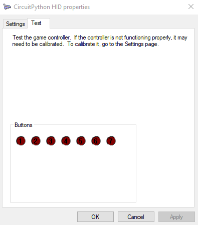
If you don't get to this point it's important to not continue to the next step.
Please look at the guides and don't be scared to ask ChatGPT for help, this took me some time, don't feel discouraged if this doesn't work right away.
----------------------------------------------------------------------------------------------------------------
Step 4: Soldering
Next I'd recommend that you would print the case. It's a little bit tight but I recommend that you place the Arduino into the box. Cut the DB9 connector off the cable, put it in the through the hole. Trim the insulation back and solder the following cables to the Arduino:
| Wire color | Arduino Pin |
| Grey | D2 |
| Red | VIN |
| Yellow | VIN |
| Orange | A0 |
| Green | A2 |
| Black | GND |
| Bare copper | GND |
| White | Unused |
| Purple | Unused |
Be careful not to cut into the cables, if you do just trim that section off and repeat. It's important to not short anything, and place a heat shrink over the bare copper cable, or like what I did, twist the black and the bare copper wire together and put heats shrink over all the cables, just make sure nothing can short circuit.
Put the lid on and connect the Arduino to your PC using a data USB C cable.
Now if you head over to “Set up USB game controllers”, you should see the following gear correspond to the correct “button” being pressed. If not you may have some color wrong or there might be a loose connection. Soldering takes time and practice, this is not easy and with the wrong equipment can make this a nightmare. Having a bad soldering iron can make a 5 minute job a nightmare so please, don't use a bad soldering iron (I have been there), buy a TS100 or TS101 and your future soldering will be a lot better.
Congratulations, now you should have a working standalone Logitech G29 shifter!
----------------------------------------------------------------------------------------------------------------
Step 5: Tuning and finalization
Next up, is to tune the code for your shifter. Mine may be slightly different from yours, therefore I recommend you open the code.py folder and look at the potentiometer values and change them to work correctly. To do that we need to change the code and look at the potentiometer values in Mu Code editor > Serial monitor.
print(f"X: {x} Y: {y} Reverse: {rev_pressed} Gear: {gear}")Place this line of code in the main loop.
Then you change to the gear that isn't working correctly and adjust the lowest and highest values you observe in the serial monitor under the “def detect_gear(x, y, reverse_pressed):” section in the code.
If you don't want to see the files open every time you plug it in add:
import storage
storage.disable_usb_drive()
to the boot.py code.
Now go out there and enjoy your shifter!
Please feel free to use this in any way you see fit!