
Open-Source Spacemouse - DFMod (v1.3 - Hall Effect & TMR support)
Obliczymy ostateczną cenę na podstawie wybranego pliku. Sprawdzisz ją i zaakceptujesz przed płatnością.
Zapisane na tym urządzeniu.

Spacemouse v2 remix with double-tap gesture, classy RGB lighting and significantly improved movement detection.
- Ocena
- 5 / 5
- Polubienia
- 86
- Pobrania
- 245
- Wydruki
- 5
- Wyświetlenia
- 2133
- Oceny
- 4
Aktualizacja u źródła:
Informacje o modelu
- Źródło
- Printables
- Kategoria
- Computers
- Licencja
- Creative Commons — Attribution — Noncommercial — Share Alike
18.12.2025: On indefinite break from Printables due to work & family - cannot provide support of any kind at the moment. My apologies & thank you for your understanding.
My variation of the open-source SpaceMouse v2, with a number of tweaks that make it feel significantly more “premium” than the original. Most of the important changes are in the software, the hardware changes are actually rather minimal. If you have an existing SpaceMouse v2 build (either a ‘vanilla’ V2 build or one based on Kempy's Smaller SpaceMouse with Hall Effect Joysticks) and don't want to mess with the hardware, you can simply flash my sketch to it as-is to get better movement, double-tap and calibration features. If you're using my sketch or building this remix please check this page from time to time - I'm occasionally pushing updates for the sketch, hardware revisions or accessories. Check the “Differences to Original” section for an up-to-date changelog.
There's two versions of my remix files, a ‘vanilla’ version and a ‘Hall Effect’ version. The vanilla version (with potentiometer sticks) requires less parts, but is more difficult to assemble, has a much bigger footprint and has more sloppy/imprecise movement with higher deadzones. The Hall Effect version requires a number of parts that can be difficult to source (including custom PCBs which have to be ordered from a PCB service), but has a nicer assembly process and has much, much better movement. I have built both versions and I strongly prefer the Hall Effect version, even though sourcing all the parts took me several weeks. If you just want to build a fun novelty controller and already have some Arduino joysticks laying around, build the vanilla version. If you want a controller that's actually useful for CAD and other 3D work, build the Hall Effect version.
There's two versions of the knob - small and big. They are interchangeable, you can use either one for either version. I've also added files for fitting TPU sleeves (to be printed with fuzzy skin), in case you prefer that handfeel. You can find them under “Accessories” in the Files section. If you want to design your own knob, make sure that it has an M22 thread at the bottom and some way for the light from the LED to pass through to the top.

Main features of my remix
Better movement! I overhauled the movement math, resulting in significantly better detection of movements. Also, the raw joystick inputs are now filtered, resulting in less noise, lower achievable deadzones and smoooooth movements that feel like they have some inertia to them. Fully adjustable in the Arduino sketch in case you're not into smoothness.
Double tap gesture! Double-tapping the knob now activates a button event. Defaults to the FIT button (recenters viewport in most programs), but can be rebound to anything you desire in the 3Dconnexion software.
RGB! But, like, in a professional, classy, non-gamer-y way, I swear. My remix uses an RGB LED in the knob to provide color-coded visual feedback for movements, gestures and calibration, through diffused backlighting.
Better calibration! Getting perfectly symmetrical axis output from potentiometer joysticks is difficult, and asymmetrical output feels really bad during use… my Arduino sketch allows for manual per-axis calibration, which - if set up properly - results in perfectly even output with full range of motion. Additionally, the auto-calibration at device startup has been reworked. It now takes more time, but provides significantly better baseline values, allowing for lower deadzones with less jitter.
Support for the ‘vanilla’ SpaceMouse v2 and for Kempy's Smaller SpaceMouse with Hall Effect Joysticks!

The new calibration routine gives visual feedback: blue flash every 10 samples. green flash every 100 samples, red flash every 1000 samples. The brightness of the white background illumination gradually increases from zero to full to indicate how long the calibration will take. RGB color sweep when the calibration has finished.
Printing
I've included .3mf files that contain all the printed parts needed to build this thing, along with print settings that should work reasonably well for X1C/P1S/P1P users. If you just want to print individual parts (e.g., if you're simply upgrading an existing Spacemouse v2 and just need the new knob assembly), there's individual .3mf files in the Files section.
Before printing, you need to decide whether you want to build a vanilla V2 version (based on TeachingTech's design) or a Hall Effect/TMR version (based on Kempy's design). You can find DFMod files for both in their corresponding folders in the Files section.
IMPORTANT:
This remix requires transparent (or translucent) filament. I used Bambu PETG Transparent for the connector piece and Elegoo Clear PLA for the knob. White filament may also work to some degree.
The knob requires an AMS/MMU. I'm working on a single filament/multiple parts version, but it's not done yet.
Some notes:
The knob can't be too heavy - use low infill for its main body. High weight can cause the joystick springs to struggle with recentering.
Same thing goes for the upper and lower dome, but it's not as critical. Still, try to keep infill reasonably low.
For the optional spacers (for the vanilla version) the opposite is true - the heavier the better. I've printed the 15mm version in colorFabb SteelFill, and it serves as weight to keep the Spacemouse stable on my desk.
Assembly (vanilla version)
Assembly is practically identical to the original v2 model, follow its instructions. The only differences are that:
The ball joints can simply be press-fitted to the joystick shafts, without the need for drilling.
You will need an RGB LED. I used a common-anode LED - adapt your wiring accordingly and change the setRGB() function in the sketch if you use a common-cathode LED.

Wire up your LED with appropriate resistors (I used 150Ω) and connect it to any three PWM-capable pins (I used 3, 5 and 10, which are conveniently free) as well as 5V.
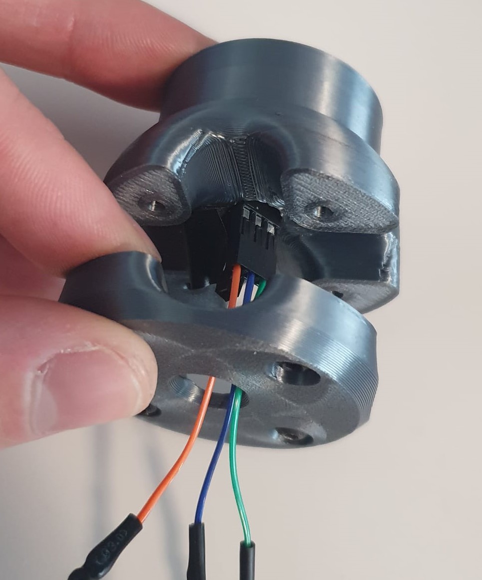

Thread the whole LED assembly through the bottom of the lower dome all the way to the lip on top of the upper dome.
Note: these pictures show me using Dupont connectors for the LED - don't. Solder the leads of the LED to the cables directly & isolate them with shrink tubing or tape. Once the LED sits at the proper location, use hot glue to fix it in place. Don't get any glue in the cavity of the dome assembly. Continue assembly as normal.
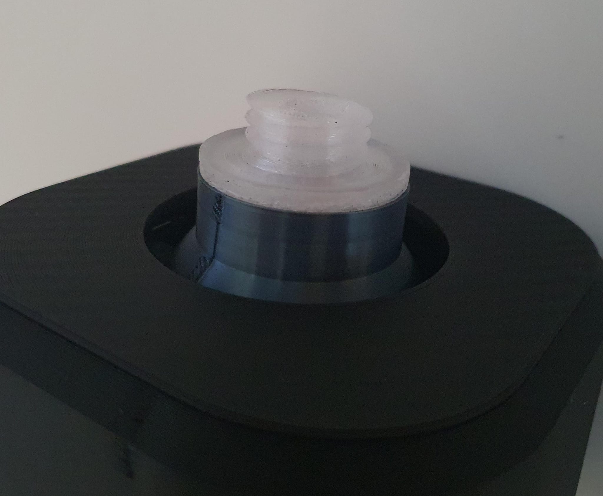

When the main assembly is finished, use CA glue to attach the connector plate to the upper dome, and thread on the knob once the glue has set.
Now it's time to set up a custom board type in the Arduino IDE. Navigate to the boards.txt file (usually at C:\Users\[yourUsername]\AppData\Local\Arduino15\packages\arduino\hardware\avr\1.8.6\boards.txt). Duplicate boards.txt and rename it to "boards.txt_backup". Then open the original boards.txt, delete all contents and paste in this:
leonardo.name=Spacemouse
leonardo.vid.0=0x2341
leonardo.pid.0=0x0036
leonardo.vid.1=0x2341
leonardo.pid.1=0x8036
leonardo.vid.2=0x2A03
leonardo.pid.2=0x0036
leonardo.vid.3=0x2A03
leonardo.pid.3=0x8036
leonardo.upload.tool=avrdude
leonardo.upload.tool.serial=avrdude
leonardo.upload.protocol=avr109
leonardo.upload.maximum_size=28672
leonardo.upload.maximum_data_size=2560
leonardo.upload.speed=57600
leonardo.upload.disable_flushing=true
leonardo.upload.use_1200bps_touch=true
leonardo.upload.wait_for_upload_port=true
leonardo.bootloader.tool=avrdude
leonardo.bootloader.low_fuses=0xff
leonardo.bootloader.high_fuses=0xd8
leonardo.bootloader.extended_fuses=0xcb
leonardo.bootloader.file=caterina/Caterina-Leonardo.hex
leonardo.bootloader.unlock_bits=0x3F
leonardo.bootloader.lock_bits=0x2F
leonardo.build.mcu=atmega32u4
leonardo.build.f_cpu=16000000L
leonardo.build.vid=0x256f
leonardo.build.pid=0xc631
leonardo.build.usb_product="Spacemouse"
leonardo.build.board=AVR_LEONARDO
leonardo.build.core=arduino
leonardo.build.variant=leonardo
leonardo.build.extra_flags={build.usb_flags}
Save, restart the IDE, connect your Spacemouse, and set the board type to "Spacemouse" in the Board/Port manager. Flash my provided sketch to the Arduino and verify that everything is working.
If you notice that the RGB colors aren't correct (should be X rotation → Red, Y rotation → Green, Z rotation → Blue, Z axis up → Magenta, Z axis down → Cyan, X translation → Orange, Y translation → Teal) then go into the sketch and change the RGB pin assignments.
Finally, go into the sketch, adjust the configuration variables to your liking, and perform calibration. Values to potentially modify are:
DEADZONE (keep as low as possible; look for the point where you start getting jitter, then set the deadzone slightly above that)
calibrationLength (how many samples to take for centering calibration)
alpha (filter setting; low → smooth, high → more responsive)
suppressDuration, tapThreshold & doubleTapWindow (settings for the double tap gesture)
AxisMaps.
On the topic of the AxisMaps: these are for manual per-axis calibration. Set debug level to 4, move all axes through their range of motion, observe the minimum and maximum values, and then write those values into the corresponding AxisMap.
Example for Z rotation:
Debug info tells me that rotating Z left to its maximum results in a value of -700, while rotating it to the right only results in +450. Go to the line “AxisMap mapRZ = …” and change the values to “AxisMap mapRZ = {-700, 450, -500, 500};”. Flash the sketch again, look at the debug info, and verify that rotating Z now gets you clean -500 to +500 output. Repeat this process for all axes.
That's it! Enjoy your SpaceMouse. Maybe go into the 3Dconnexion settings and play a bit with the settings. If you want to change the mapping of the double tap gesture, you can change it to anything you'd like there.
Assembly (Hall Effect version)
If you're building the Hall Effect version you're probably comfortable with things like ordering custom PCBs and thus more advanced, so I'll keep this section short. Print my remixed parts, then follow Kempy's build instructions. Before closing up the frame, hook up a Common Anode RBG LED to pins RAW, 3, 5 and 10 on the PCB, with appropriate resistors between the RGB pins and your Arduino. 120Ω-150Ω should be fine, but check your LED's specs and do your own calculations! Glue the connector to the upper dome, thread the LED through the holes in the dome piece, verify that the cables don't interfere with the ball joints, then fix the LED in its place in the connector with CA glue or hot glue. Screw on the knob, and assembly is done.
Set up the custom board type, load my sketch in your IDE and start tweaking values. DEADZONE can be set significantly lower than default (for my Hall Effect sticks, 4-8 works great). CalibrationLength and CalibrationRestPeriod can both be set to 10, Hall Effect sticks do not require calibration. TapThreshold and TapCooldown need to be tweaked, play around with the values with debug level 4 to find settings that allow you to activate double tap reliably. AxisMaps are not really relevant for the Hall Effect version; you can probably skip calibrating them and just use the defaults (or simply use them to do custom axis shaping).