
BTT PI TFT50 V2.1 Prusawire housing
Obliczymy ostateczną cenę na podstawie wybranego pliku. Sprawdzisz ją i zaakceptujesz przed płatnością.
Zapisane na tym urządzeniu.

BTT PI TFT50 V2.1 housing for Prusawire in Prusa-style design.
- Ocena
- 5 / 5
- Polubienia
- 14
- Pobrania
- 38
- Wydruki
- 1
- Wyświetlenia
- 472
- Oceny
- 1
Aktualizacja u źródła:
Informacje o modelu
- Źródło
- Printables
- Kategoria
- Prusa Parts & Upgrades
- Licencja
- GNU General Public License v3.0
FOR BTT PI TFT50 V2.1!
Print instructions
Cover, back plate and supports can be printed from ASA, ABS, PETG, PLA or any other suitable material. Buttons are highly recommended to be printed from PETG or other flexible material. No supports needed :)
Print also the included modified front_grill_left part that has hole for DSI-cable to go through.
I printed mine from Prusament ASA (galaxy black, Prusa orange and signal white), Fillamentum ASA white aluminium and Prusament PETG galaxy black.
Required hardware
7 pcs M3x8 BHCS
2 pcs M3x6 BHCS
12 pcs M3 Threaded Insert - M3x5x4 (Voron spec)
1 pc M3 square nut
4 pcs display mounting screws that come with the display
Assembly instructions
Preparing the right support

Insert 4 threaded inserts, circled with yellow.
Preparing the left support

Insert 4 threaded inserts, circled with yellow. Insert 1 square nut, circled with green.

Fix the two halves of the left support together with M3x6 BHCS, circled with yellow. This is also good point to insert DSI-cable inside the support but it can be pushed through afterwards.
Preparing the back plate
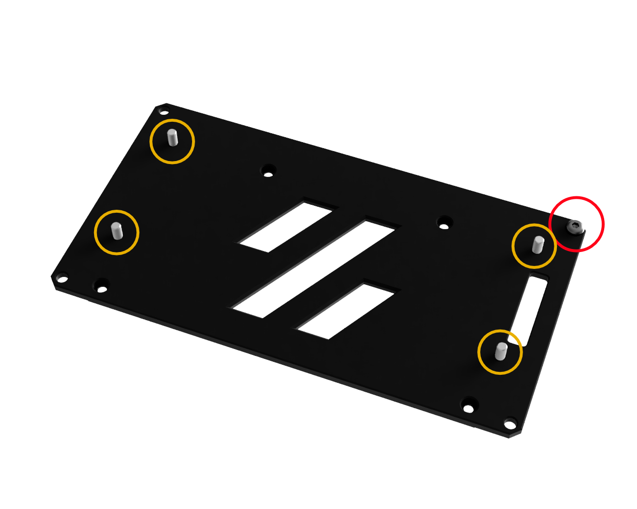
IMPORTANT! Insert M3x6 BHCS (red circle) before installing the left support as the screw can't be inserted after the support is in place. Note also that it is inserted from other side compared to support mounting screws (yellow circle).
Mounting the supports
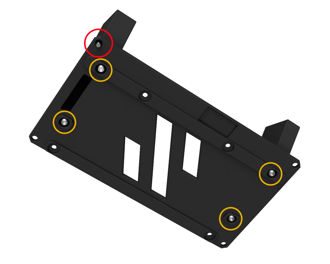
Fix the supports in place with 4 M3x8 BHCS (yellow circle) and double check that you remembered to insert one M3x6 BHCS in the previous step (red circle).
Mounting BTT PI TFT50 V2.1
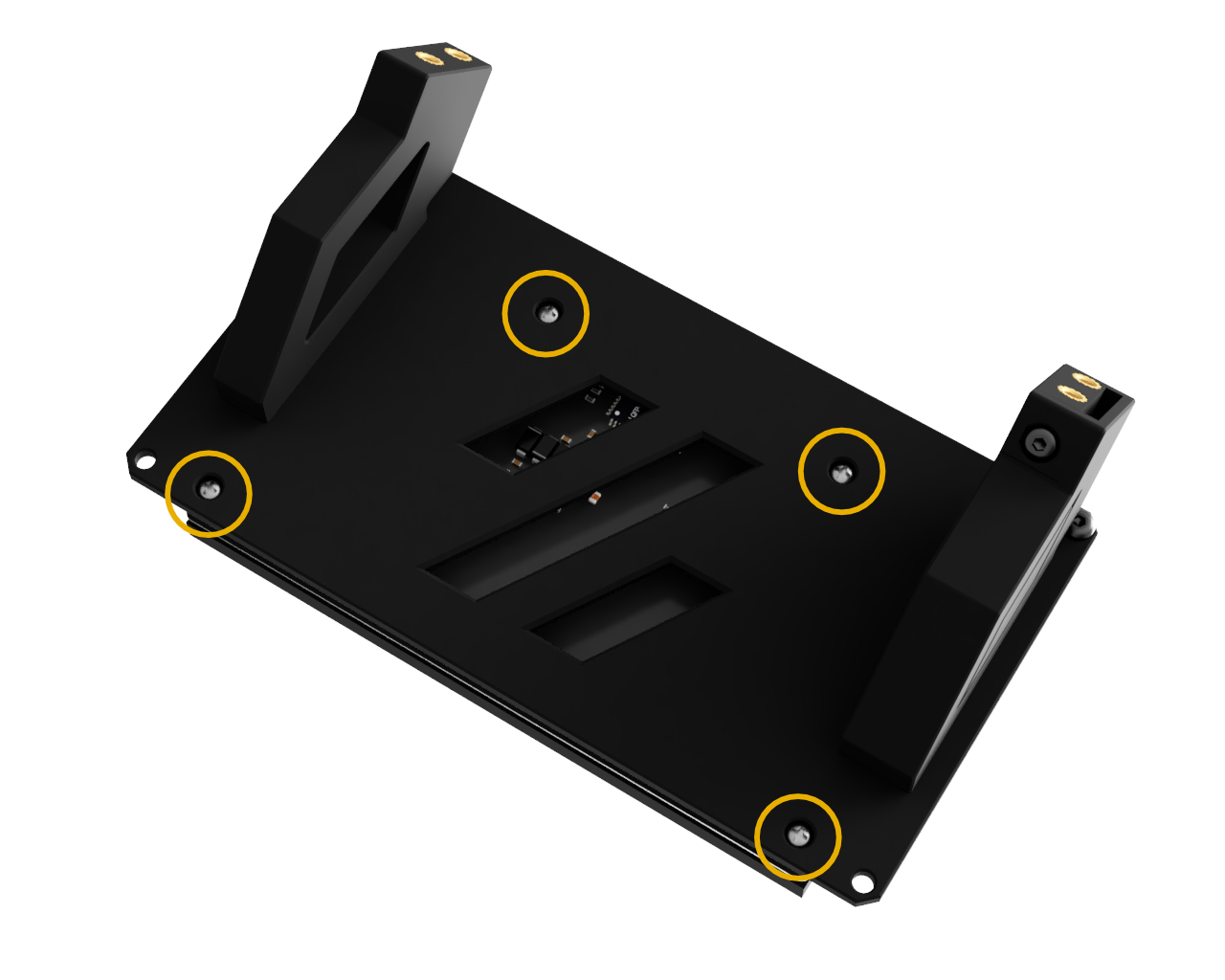
Connect the DSI cable to the display and fix the display to the back plate with 4 screws that came with the display (yellow circle).
Preparing the cover

Insert 4 threaded inserts, circled with yellow. Slide the buttons in to the slot in the cover (green circle).
Mounting the cover

Fix the cover in place with three M3x8 BHCS (yellow circle) and tighten the previously inserted M3x6 BHCS (dashed red circle).