
Ham Radio CW Touch Paddle - UNDER $10
Obliczymy ostateczną cenę na podstawie wybranego pliku. Sprawdzisz ją i zaakceptujesz przed płatnością.
Zapisane na tym urządzeniu.

Made my own touch paddle from amazon stuff and 3d printed the case... you're welcome to make one for yourself.
- Ocena
- 0 / 5
- Polubienia
- 0
- Pobrania
- 22
- Wydruki
- 1
- Wyświetlenia
- 274
- Oceny
- 0
Aktualizacja u źródła:
Informacje o modelu
- Źródło
- Printables
- Kategoria
- Other Gadgets
- Licencja
- Creative Commons — Attribution — Noncommercial — NoDerivatives

Download the .pdf file too. Drawing and Bill of Material!!!
I built this prototype for a touch paddle, and it works great. This is ham radio baby! No warranties, guarantees or otherwise. As always, you're on your own! Make your connections with those pre-made pin connection wires if you want… whatever they're called, or just solder it up. Soldering done outside the plastic case is preferred, then stuff everything in and superglue it! Anyway, had to have a few volts to power the capacitance touch sensors(get the ones setup not to toggle) so the Li-ion battery(the 18650 cell is the most expensive thing @$3 ea). But the little charge controller board is cheap with nice little LEDs(red&blue)indicating charging state. Mine topped out at 4.07 volts when it indicated full charge… I haven't run it all the way down, but fresh out of the package was 3.53 volts.
Cheap and plentiful on amazon…buy quantities and give your club kits to build and they'll vote you into high office. So when you get done, and it's all working, you'll have satisfaction in knowing you're one of the few with bright green LEDs on your CW paddle.
Hams don't need wiring diagrams, you'll figure it out. Basically, you just need to get the positive side of the battery to VCC pins on the touch sensors by way of your on/off toggle switch. Then get the ground back to battery negative. Now your touch sensors are powered.
IO from each of the touch sensors needs to go through 500 to 1000 ohms (I used 1000, but the 817 is rated for 50mA so you could get away with 100 maybe)before going to pin 1 of its respective optocoupler. Both pin 2s need to go to battery negative.
Both pin 3s need to go to jack negative - the long pin on jack. Then each pin 4 needs to go to its respective side of the jack. If you get them backwards left/right right/left, you'll just have to flip the paddle over in your hand for dits and dahs instead of dahs and dits. That should get you there. Simple.
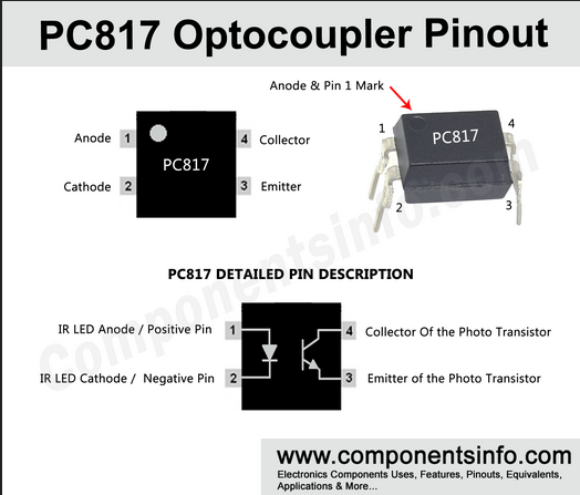
Hint - make sure the optocouplers inputs and outputs are correct and are in the right direction! Ground for the input side of the optocouplers needs to get back to battery negative… ground for the output side of the optocoupler needs to go get to the ground pin on the jack/plug.