
Model of Marcel Duchamp's Bicycle Wheel by william Cromar: Full Scale Edition
Obliczymy ostateczną cenę na podstawie wybranego pliku. Sprawdzisz ją i zaakceptujesz przed płatnością.
Zapisane na tym urządzeniu.
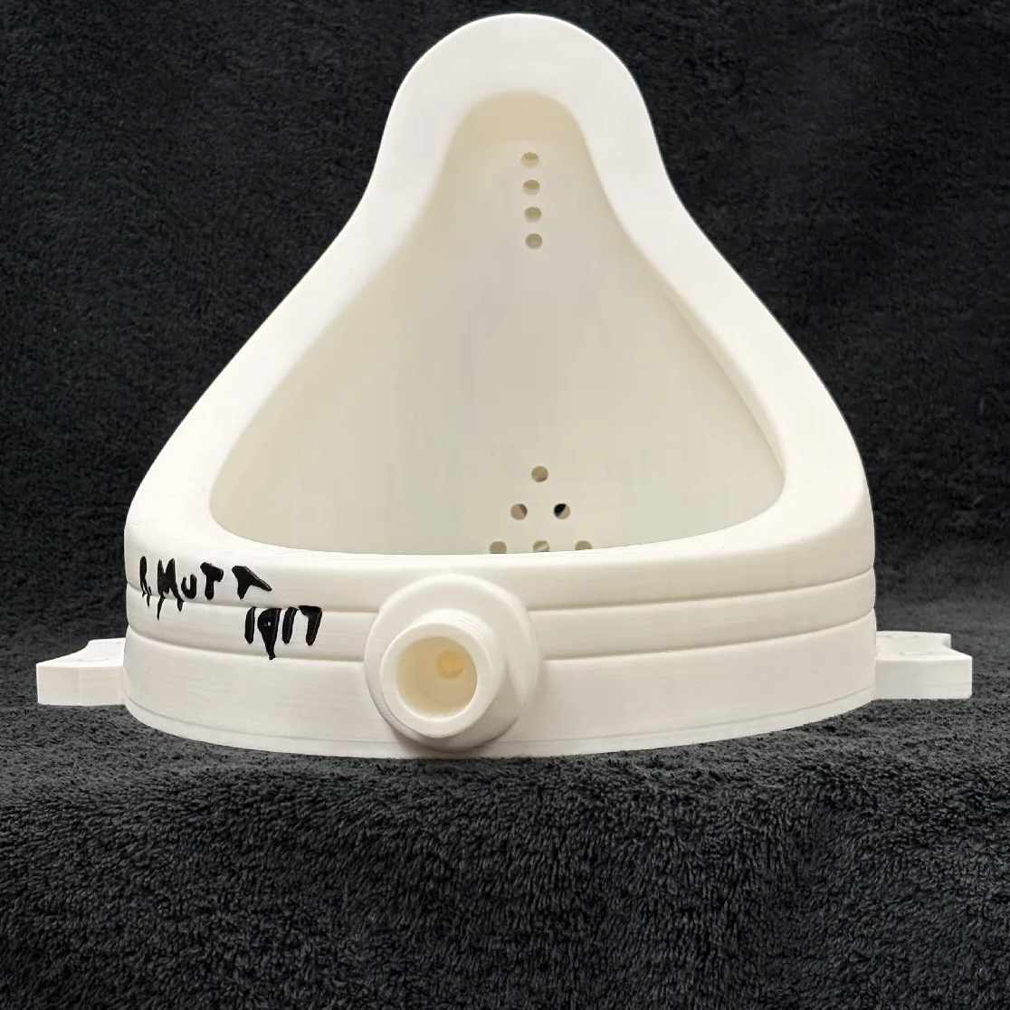
Full-scale plating of Model of Marcel Duchamp's Bicycle Wheel by williamCromar in a Club-exclusive marketplace critique.
- Ocena
- 0 / 5
- Polubienia
- 2
- Wydruki
- 0
- Wyświetlenia
- 242
- Oceny
- 0
Aktualizacja u źródła:
Informacje o modelu
- Źródło
- Printables
- Kategoria
- Sculptures
- Licencja
- Standard Digital File License
🚲🚲🚲🚲🚲🚲🚲🚲🚲🚲🚲🚲🚲🚲
Interviewer, George Hamilton: Do you think anybody else could make one?
Marcel Duchamp: Yes, everybody can! Every century there is a new definition of art. So if we accept trying not to define art then the readymade comes in as a sort of irony, because here it is, a thing that I call art.
🚲🚲🚲🚲🚲🚲🚲🚲🚲🚲🚲🚲🚲🚲
This digital asset is a refined, full-scale manifestation developed as part of an instructional research initiative supported by a faculty grant from Penn State Abington and the Abington MakerSpace. It expands upon the geometric parameters established in the public open-access reference collection Prêt à Faire: Printable Readymade Models.
Video of finished full-size functional print demonstrating the wheel base rotation and spin
1 | Concept & Provenance
This asset is an autonomous work of conceptual art: a 1:1 scale digital study of the physical parameters underlying the famous Bicycle Wheel (1913) by Marcel Duchamp. The historical original work is lost; this model stands as an independent, transformative interpretation that cross-references the public dimensional layout documented by the historical 1964 Galerie Schwarz variant.
Duchamp stated, “Yes, everybody can” make one. This project literalizes that claim by distributing the underlying structural geometry through contemporary digital fabrication networks. While the physical print may resemble a familiar historical motif, the conceptual artwork resides in the publication and curation of the digital models themselves: the digital architecture, the distributed network framework, and the marketplace critique. The printed object is a physical manifestation, not the artwork proper.
Fabricating this model additively from a published digital archive—rather than manually assembling found objects—situates it firmly within a contemporary critique of distributed culture. The visible layer lines, tolerances, and physical print artifacts are therefore intentional and conceptually integral.
Before printing, explore the historical context of the referent at:
Sample images of historical replicas:
 Philadelphia |  MoMA |  Duchamp's NYC studio |
The historical visual motifs analyzed here have been famously referenced or appropriated by legions of contemporary artists, including but not limited to:
Elaine Sturtevant created a historical physical replica referencing the wheel and stool dimensions.
Richard Pettibone created an army of multiples.
Ji Lee reverted it to its original context.
 Elaine Sturtevant, Duchamp Bicycle Wheel, 1969-73 |  Richard Pettibone's studio, 1965 |  Ji Lee, Duchamp Reloaded, 2009 |
2 | Scope & Scale
As a work of Post-Appropriation and remix praxis, this model is an independent digital manifestation optimized specifically for full-scale FDM fabrication, structural durability, and mechanical assembly. The geometry deliberately adapts historical visual motifs into a printable medium, celebrating the physical deviations required by the additive manufacturing process as part of the artwork's transformative expression:
It is designed to be printed at full historical scale.
Changing scale is not recommended, as it will compromise tolerances, bearing fits, and structural behavior.
Many parts require a large-format printer such as a Prusa XL.
A smaller, scalable open-access reference version is available at this link.
3 | Printing Notes
3.1 | General Recommendations
Use the supplied 3MF files with preconfigured orientations and settings.
These settings were validated on a well-tuned Prusa XL using dehydrated filament.
STL and STEP files are provided for users who wish to experiment.
If creating your own build plates, print extra spokes, nipples, and rim registration pieces.
File Formats
[Model_Name].3mf/.stl→ Best for quick printing. Pre-meshed at a high resolution, these files will slice exactly as they appear in the smooth website preview.[Model_Name].step→ Best for remixing and maximum quality. These files contain precise CAD data. Note: Ignore the blocky look in the online browser viewer; it will download and slice with perfectly smooth mathematical curves inside your slicer.
Part Naming Convention
Leading number: Part ID (matches tables below)
Name of part with orientation (left or right, front or rear, top or base)
Trailing number: Quantity to print (if no trailing number, print one)
Designed Tolerances
Friction fit: ~0.1 mm
Tight glue joints: ~0.2 mm
Moving parts: ~0.4 mm
Actual results depend on your printer calibration. Prototype fit-sensitive parts before committing to final prints; use the prototype 3MF file for testing. The best fine-tuning solution is to tweak the Extrusion Multiplier (a.k.a. flow rate) setting under the Filaments tab:
If the part is too loose, increase the value in 0.05 increments until fit is achieved
If the part is too tight, decrease similarly.
For example, we needed to increase the value to 1.15 to achieve the proper fit for the threads connecting spokes to nipples. NOTE: Your results WILL vary based on machine and material.
Observed Issues in Our Prototyping
No significant shrinkage was observed, but occasionally, tweaking Extrusion Multiplier values was necessary to achieve a proper fit
No curling on large parts, such as the seat
~8% failure rate on spokes due to curling; mitigated by adding a helper disk to each end
Brims are NOT recommended on spokes
When prototyping for fit, use the filament you intend to use for the final product. We found significant differences among the filaments we tested below.
3.2 | Material Recommendations
For filament, consider the following:
Metallic Silver:
Axle components
Spokes and nipples
Fork nuts and washers
Recommended PLA:
Prusament PLA Galaxy Silver
Atomic Metallic Silver V2 PLA
Polymaker Panchroma Metallic Silver PLA
Advanced options for metal-flake PLA (abrasive-resistant nozzle required):
Proto-Pasta Stainless Steel PLA
ColorFabb SteelFill PLA Filament
Glossy Black:
Fork parts
Rim parts
Recommended PLA:
Prusament PLA Galaxy Black
Bambu Lab PLA Sparkle Black
Protopasta HT PLA Empire Strikes Black Glitter
Cookiecad PLA Star Dust Black
ZIRO PLA Diamond-Black
Warm Off-White:
Stool parts
Recommended PLA:
Prusament PLA Vanilla White
Polymaker PolyLite PLA Cream
eSUN PLA+ Bone White
American Filament PLA Ivory White
Jigs:
Any PLA
Additional material recommendations:
Two standard 8 x 22 x 7 bearings
Adhesives: PLA solvent (e.g., Gloop, Weld-On 16) and/or fresh, slow-dry gel CA
3.3 | Printing Statistics
Prototype 3MF
Contains one instance of each tolerance-critical part for testing in one file:
~650 g filament, distributed across the various filaments used for the final work
~31 hr print time
2 build plates
Full-Scale Print
Total filament: ~2500 g
Stool: ~1540 g
Fork + rim: ~595 g
Spokes + axle: ~161 g
Jigs: ~218 g
Total time: ~165 hr (≈7 days)
Build plates: 15
Stool: 6
Fork: 1
Spokes + axle (with fork nut-washers): 3
Rim: 4
Jigs: 1
NOTE: Stool legs were printed with higher infill to lower the center of gravity. Reducing infill decreases print time but increases tipping risk.
4 | Parts Breakdown
Parts feature an embossed reference number, with a few exceptions as described below :
* These parts may be printed on a smaller printer. Duplicate the 3MF file, change the printer profile, delete parts that require the large print bed, and reorganize.
** These small silver parts are grouped with similar parts in another file.
*** Quantity shown is the correct number needed, but print a few extras.
**** Part does not have a label but can be recognized by shape or symbol; print spoke groups on separate plates and keep them segregated to avoid confusion.
STOOL
ID# | Name | Quan | Plate in 3MF |
|---|---|---|---|
1A | Seat top | 1 | 1 |
1B | Seat base | 1 | 2 |
1C | Seat registration * | 1 | 3 |
2A | Leg spine * | 8 | 3 |
2B | Leg base exterior * | 4 | 4 |
2C | Leg base interior * | 4 | 4 |
2D | Leg mid exterior * | 4 | 5 |
2E | Leg mid left-front and right-rear interior * | 2 | 5 |
2F | Leg mid right-front and left-rear interior * | 2 | 5 |
2G | Leg top exterior * | 4 | 4 |
2H | Leg top interior * | 4 | 4 |
3A | Rung top left-right exterior * | 2 | 6 |
3B | Rung top left-right interior * | 2 | 6 |
3C | Rung top front-rear exterior * | 2 | 6 |
3D | Rung top front-rear interior * | 2 | 6 |
3E | Rung base left-right exterior * | 2 | 6 |
3F | Rung base left-right interior * | 2 | 6 |
3G | Rung base front-rear exterior * | 2 | 6 |
3H | Rung base front-rear interior * | 2 | 6 |
FORK
ID# | Name | Quan | Plate in 3MF |
|---|---|---|---|
4A | Fork crown and steering tube * | 1 | 1 |
4B | Fork leg | 2 | 1 |
4C | Fork leg registration | 2 | 1 |
4D | Fork mounting plate * | 1 | 1 |
4E | Fork base collar * | 1 | 1 |
4F | Fork top nut/washer * | 1 | 1 on spoke/axle ** |
4G | Fork base nut/washer * | 1 | 1 on spoke/axle ** |
4H | Fork hole cap * | 2 | 1 |
4J | Fork base registration * | 1 | 1 |
SPOKE/AXLE
When printing 5E1 and 5F1, note the presence of a pre-modeled support ring.
ID# | Name | Quan | Plate in 3MF |
|---|---|---|---|
5A | Axle * | 1 | 1 |
5B | Axle bearing cover * | 2 | 1 |
5C | Axle bearing cover registration * | 2 | 1 |
5D | Axle spoke interior hub * | 2 | 1 |
5E1 | Axle spoke front exterior hub * | 1 | 1 |
5EF2 | Axle spoke exterior hub * | 2 | 1 |
5F1 | Axle spoke rear exterior hub * | 1 | 1 |
5G | Axle washer * | 2 | 1 |
5H | Axle nut * | 2 | 1 |
6A | Interior spoke ***** | 18 *** | 2 |
6B | Exterior spoke ***** | 18 *** | 3 |
6C | Spoke nipple * ***** | 36 *** | 1 |
RIM
Because the spoke pattern is nonagonal, therefore not rotationally symmetrical, each rim piece is unique! Keep them in the proper order for assembly. Use the valve hole as a datum to orient the assembly.
ID# | Name | Quan | Plate in 3MF |
|---|---|---|---|
7A | Rim upper left front (with hole) | 1 | 1 |
7B | Rim upper right front | 1 | 2 |
7C | Rim lower right front | 1 | 3 |
7D | Rim lower left front | 1 | 4 |
7E | Rim upper right rear (with hole) | 1 | 1 |
7F | Rim lower right rear | 1 | 2 |
7G | Rim lower left rear | 1 | 3 |
7H | Rim upper left rear | 1 | 4 |
7IA | Rim long registration * | 35 *** | 1 |
7IB | Rim short registration * | 2 *** | 1 |
JIGS
ID# | Name | Quan | Plate in 3MF |
|---|---|---|---|
5Y | Axle spoke hub gluing jig | 1 | 1 |
7X | Rim clamp gluing jig | 8 | 1 |
7Y | Axle tensioning jig | 1 | 1 |
7Z | Rim tensioning jig | 3 | 1 |
5 | Assembly Notes
5.1 | Orientation Nomenclature
Front/Rear = A view perpendicular to the wheel disk
Left/Right = A view parallel to the wheel disk
Interior/Exterior = A piece located inward or outward from the center of the work
Base/Mid/Top: Vertical stacking order
 |
5.2 | Bearings
Apply a small amount of light lubricant (Tri-Flow or similar)
Wipe excess before assembly
5.3 | Adhesives & Tools for All Steps
Adhesives
Use PLA solvent (e.g., Gloop) or fresh gel CA
Clamp or compress until fully cured
Avoid adhesives on bearings and moving interfaces
Tools
Clamps, removable tape
Small brushes, trays for gluing
Needle or paper clip (for gluing small spaces)
#11 craft knife
Needle-nose pliers, tweezers
Color markers or tape for labeling spokes
Safety
Standard PPE: Nitrile gloves, eye protection
Ventilation when using solvents
Remember, you are assuming all risk when using these materials and files, so stay safe!
6 | Stool Assembly
6.1 | Rung Assemblies
Parts:
Rung halves (3A-3H)
Procedure:
Glue the following pairs: 3A–3B, 3C–3D, 3E–3F, 3G–3H.
Clamp until cured.
Result:
4 top rungs (2 3AB, 2 3CD)
4 base rungs (2 3EF, 2 3GH)
 6.1 Rung assembly |  6.2 Parts for one leg assembly Middle row: 2A, 2A Bottom row: 2B, 2E or 2F, 2H |
6.2 | Leg Assemblies (Repeat × 4)
Parts:
2X Leg spine (2A)
Leg base exterior (2B) and interior (2C)
Leg mid exterior (2D) and interior (2E OR 2F)
Leg top exterior (2G) and interior (2H)
Procedure:
Glue spine into base exterior slot, flush and angle-matched.
Glue the base interior over the spine.
Glue the mid interior on the same side as the base interior.
Insert the second spine.
Glue the mid exterior.
Glue the top exterior.
Glue the top interior.
Clamp until cured.
Result:
4 completed leg assemblies.
 6.2.2 |  6.2.3 |  6.2.4 |
 6.4.6 |  6.4.7 |  6.2 All leg assemblies |
6.3 | Leg Frame Assembly
Parts:
8 rung assemblies from above.
4 leg assemblies from above.
Procedure:
Glue 3AB left-right top rung assembly into the highest notch on one leg assembly (see illustration).
Glue 3EF into the notch below that (the second-lowest notch, see illustration).
Glue a second leg assembly to the other side of the rungs.
Repeat for the second pair of leg assemblies.
Connect both leg assembly pairs using the remaining top (3CD) and base (3GH) rung assemblies.
Result:
Complete 4-leg frame.
 6.3.1 — 4 |  6.3.5 |
6.4 | Seat and Finished Stool Assembly
Parts:
Seat top (1A)
Seat registration (1B)
Seat base (1C)
Finished 4-leg frame assembly
Procedure:
Glue the seat registration (1C) to the seat base (1B).
Glue the seat top (1A) to the above assembly.
Glue the 4-leg frame into the seat base from below.
Result:
Completed stool.
 6.4.1 and 2 |  6.4.3 |  6.4 Completed stool |
7 | Fork Assembly
Parts:
All fork parts (4A-J)
NOTE: You may use the alternate split fork crown and base collar provided in the 3MF file to reduce support for these parts.
Procedure:
Glue fork registrations (4C) and base registration (4J) into the crown (4A).
Glue fork legs (4B) onto the crown. Fit should be very snug, as illustrated on the RIGHT fork leg.
Slide on and glue the top nut-washer (4F) onto the crown.
Insert the crown into the stool seat; do not glue! Allow to spin freely.
Glue the base nut-washer (4G) onto the base collar (4E).
Glue the base collar (4E) onto the crown from below, ensuring a snug fit to allow rotation without bending.
Do not glue fork hole caps (4H) yet.
Result:
Completed fork/stool assembly.
 7 All fork parts |  7.1 |  7.2 |
 7.3 |  7.4 |  7.5 — 7 |
8 | Wheel Assembly
8.1 | Axle Assembly
Parts:
All axle parts (5A-H)
Bearings
Procedure:
Glue bearing cover registrations (5C) into one bearing cover (5B).
Glue the second cover over the cover registrations.
Press one bearing onto the axle (5A), between registration lines on the axle.
Install bearing cover assembly and test for fit. If you need to adjust, reprint using Extrusion Multiplier (flow rate) values: higher for a tighter fit, lower for a looser fit. Glue the bearing casing into the cover only if required.
Press the second bearing onto the axle, between registration lines.
Glue interior spoke hubs (5D).
Using the gluing jig (5Y), assemble the two halves of the front (5E1, 5EF2) and rear (5F1, 5EF2) exterior spoke hubs, then glue each in place against the interior spoke hubs and label them for later spoke installation.
Place washers (5G) and nuts (5H) temporarily.
Result:
Completed axle assembly, spinning freely.
 8.1 All axle parts |  8.1.1 and 2 |  8.1.3 |
 8.1.4 |  8.1.5 |  8.1.6 |
 8.1.7 |  8.1.8 |  8.1 Axle assembly |
8.2 | Spoke/Axle Assembly
Parts:
Interior spokes (6A), indicated by a dimple on the hook
Exterior spokes (6B), indicated by a raised bump on the hook
Procedure:
Threading order on the spoke hub:
9 rear interior (seen in RED); hook faces out, spoke is inside hub.
9 front interior (YELLOW); hook out, spoke inside.
9 rear exterior (BLUE), hook in, spoke outside.
9 front exterior (GREEN); hook in, spoke outside.
Lacing in a 3-cross lacing pattern:
Organize spokes so that each spoke crosses three others.
Lacing at the third crossover reverses the interior/exterior relationship.
Secure the crossovers temporarily with tape.
Result:
Completed spoke/axle assembly.
 8.2.1.1 RED: 9 rear interior spokes (6A) |  8.2.1.2 YELLOW: 9 front interior spokes (6A) |
 8.2.1.3 BLUE: 9 rear exterior spokes (6B) |  8.2.1.4 GREEN: 9 front exterior spokes (6B) |
Click on images to enlarge, and notice the pattern: RED and BLUE are at the rear; YELLOW and GREEN are at the front. Use colored markers or tape to label them at the outer tip end.
 8.2.2 Rear lace |  8.2.2 Front lace |  8.2.3 Crossover taping |
8.3 | Rim Assembly
Parts:
Front: 7A (with valve hole), 7B, 7C, 7D
Rear: 7E (with valve hole), 7F, 7G, 7H
Rim registration pieces (7IA, 7IB)
Rim clamp gluing jigs (7X)
Procedure:
Glue registration pieces (7IA, 71B) into all front parts (7A-D). NOTE: The short registration pieces are adjacent to the valve hole.
Using the rim clamp gluing jigs (7X), glue 7A to the tabs at 7E, aligning the valve holes. Continue using the gluing jigs for all remaining rims.
Glue 7H to the tabs at 7A and the joint at 7E
Glue 7B to tabs at 7E and joint at 7A
Glue 7D to tabs at 7H and joint at 7A
Glue 7G to tabs at 7D and joint at 7H
Glue 7C to tabs at 7G and joints at 7B and 7D
Glue 7F to tabs at 7B and 7C and joints at 7E and 7G (F is last because it has a special joint allowing it to lie in and close the circle.
Result:
Completed rim assembly.
 8.3 All rim parts |  8.3.1 |
 8.3.2 |  8.3.3-8 |
8.4 | Wheel Assembly and Tensioning
Parts:
Tensioning jig parts (7Y-Z)
Spoke/axle assembly
Rim assembly
Procedure:
Assemble tensioning jig (7Y, 7Z).
Seat the rim in the jig with the rear parts (7E-H) facing up and the valve hole centered on one rim tensioning jig as seen in the illustration.
Insert the axle assembly with the rear spokes (RED and BLUE) facing up.
Align a RED spoke with the spoke hole to the left of the valve hole, designating it as #1 of 9. Other RED spokes will count clockwise, as illustrated.
Designate other spokes similarly in all other groups, as illustrated.
Screw nipples onto spoke threads in groups, tightening by hand, then adding tension with a screwdriver without overtightening:
Rear: RED 1, 4, 7 → BLUE 1, 4, 7
Front: YELLOW 1, 4, 7 → GREEN 1, 4, 7
Repeat steps 5 and 6 for spokes 2, 5, and 8 in all groups.
Repeat for all remaining spokes in all groups.
Result:
Completed wheel assembly with tensioned spokes.
 8.4.1 |  8.4.2 |  8.4.3 |
 8.4.4-5 | ||
 8.4.6.1-2 |  8.4 Wheel assembly | |
9 | Final Integration
Parts:
Fork/stool assembly
Wheel assembly
Procedure:
Remove axle nuts.
Remove fork hole caps.
Insert the axle into the fork, aligning the flat surfaces.
Ensure minimal washer play, using paper as a removable shim.
Glue fork hole caps to secure the axle.
Press axle nuts into place, lightly gluing if needed.
Result:
Completed final assembly.
 9.1 |  9.2 |  9.3 |
 9.4 |  9.5 |  9.6 |
 9 Final assembly | ||
10 | Testing and Truing
Allow full cure overnight.
Grasp the rim, give the wheel a gentle spin, and observe for wobbling.
A minor amount of wobbling is acceptable.
If a large wobble is detected, inspect the spokes for any with poor tension.
Use a screwdriver to tighten spokes with poor tension; do not over-tighten! The goal is to achieve relatively uniform tension among all spokes, which will true the wheel alignment.
11 | Presentation Notes
Place on the floor or a low pedestal.
Consider affixing feet to the mounting surface with museum wax for additional stability.
The work is meant to be handled! Encourage spectators to spin the wheel by the rim, not the spokes. If a modular spoke breaks due to mechanical handling, it is engineered to be easily replaced without destructive disassembly, as it remains unglued within the hub interfaces.
12 | Support
Access to this file facilitates your active engagement with the project's broader marketplace critique. Fabricating a 1:1 scale operational kinetic system using additive manufacturing involves navigating complex structural and tolerance thresholds. We provide direct technical support through the platform messenger to assist you in resolving any advanced fabrication or slicing inquiries you encounter. Thank you for participating in this distributed institutional inquiry!
13 | Change Log
28 JUN | Re-ordered parts listings for a better previewing experience. While the STEP files are mathematically precise, the browser renders them janky, so STL files are seen first.
9 MAY | Revisions to architectural geometry:
Improved structural design for all 7A-H rim components and 7I rim registration parts, including updated technical illustrations.
Added custom rim gluing jigs. Included a GIF and video documentation of the finalized physical build, demonstrating independent fork rotation and kinetic wheel spin.
22 MAR | Revised part 7F and instructions for assembling the rim for improved workflow when gluing these tricky parts together. Updated 3MF and PDF to reflect the change.
10 MAR | Revisions to core file structures:
Improved 5E and 5F spoke hubs to ensure consistent slicing and extrusion tolerances across the full range of recommended filaments.
Optimized geometric paths to implement standard slicing support structures.
Refined the mechanical interface between the stool top and bottom components for a flush, stable fit.
Generated a formatted comprehensive reference PDF.
Added an updated exploded-view rendering indexing all modified components.
28 FEB | Implemented minor tolerance improvements to custom slicing parameters in all preconfigured 3MF files. Added an alternative orientation scheme to the fork crown 3MF to minimize mechanical support requirements. Expanded the technical discussion regarding prototyping workflows and adjusting Extrusion Multiplier variables to manage tight mechanical press-fits.
20 FEB | Revisions as follows:
Implemented structural adjustments to the seat-fork interface based on cross-referenced art-historical documentation below.
Refined the geometric joint between the fork collar and structural legs to ensure a precise mechanical fit.
Engineered a new thread-tensioned spoke-nipple configuration for improved physical stability and wheel truing.
Expanded technical instructions to highlight specific Extrusion Multiplier thresholds required to clear the threaded profiles.
Updated all master 3MF assets to incorporate these file revisions.
Contextual Research Update:
Historical documentation found in Duchamp: Love and Death, Even by Juan Antonio Ramirez brought to light this photographic reference material:

The historical image indicates that the structural alignment of the wheel mechanism was capable of dynamic rotation relative to the base. I have updated the independent stool and fork file geometry to allow for this variable motion within the model's structural framework.
12 FEB | To optimize physical print quality and layer orientation, structural components 5E and 5F were split into individual files, accompanied by a custom assembly alignment jig. Tightened dimensional tolerances across all primary axle components. Compiled an updated technical parts index for associated assembly jigs.
Disclaimer
Prêt à Faire is an autonomous artistic project, scholarly reference work, and institutional critique by williamCromar, supported by a faculty grant from Penn State Abington with fabrication assistance from the Abington MakerSpace. This project is entirely independent and maintains no formal affiliation, endorsement, or sponsorship with Association Marcel Duchamp, the Estate of Marcel Duchamp, ARS, ADAGP, or any curating museum. When referencing or sharing this work, users must maintain a clear distinction in authorship and nomenclature from the historical referent. Cite this asset as: Model of Marcel Duchamp’s [Object Name] by williamCromar. Basic models are available under a CC BY-NC-SA 4.0 license; premium tiers operate under a separate commercial framework. For full conceptual and legal text, visit https://sites.psu.edu/pretafaire/disclaimer-and-licensing/