
PicoUsbLedStrip enclosure
Obliczymy ostateczną cenę na podstawie wybranego pliku. Sprawdzisz ją i zaakceptujesz przed płatnością.
Zapisane na tym urządzeniu.

A simple enclosure for Raspberry Pi Pico RGBA LED controller.
- Ocena
- 0 / 5
- Polubienia
- 2
- Pobrania
- 6
- Wydruki
- 0
- Wyświetlenia
- 39
- Oceny
- 0
Aktualizacja u źródła:
Informacje o modelu
- Źródło
- Printables
- Kategoria
- Electronics
- Licencja
- Creative Commons — Attribution
Introduction
The motherboard I have does not come with an integrated addressable RGB LED (RGBA) controller, and I wanted one that I could control from the PC directly off of a spare USB header on the motherboard.
My natural choice was either a Raspberry Pi Pico or an Arduino, but since I've found a cool project by Disciple153 on GitHub, I decided to try it out.
The project doesn't have a printable case model, so I decided to make one myself. And since I didn't really need the Spectrum Analyzer mode (nothing to analyze but fan noise inside the case), I decided that a simplistic enclosure with a microUSB input and two connectors for the RGBA strip and LED power would suffice.
Parts and Materials Needed
Raspberry Pi Pico 2040
XH-2A header for LED power
XH-3A header for RGBA connector cable
2k2 resistor
A length of 20-22 AWG wire for internal connections
4x M2x5mm screws
XH-2Y terminated cable with a 5V connection from the case PSU (e.g., SATA power connector red and black wires)
XH-3Y terminated cable with an RGBA connector
Motherboard USB2 header to microUSB cable
1.75mm translucent filament strip for Pico heartbeat LED lightguide
Cyanoacrylate glue
Printing and Assembly
The case was printed in PETG using “0.20mm Quality” preset with paint-on supports for headers and Pico microUSB connector.
Assembly can be done in the following order:
After printing insert and fix the XH-3A and XH-2A headers in the corresponding pocket using glue.
Take a ~5mm piece of 1.75mm translucent filament and insert it into the small hole in the case cover near microUSB input, fix using pocket glue if needed.
Solder a 2k2 resistor to pull the analog input used in the original design for the spectrum analyzer mode to ground.
Solder data out pin and ground wires to the Pico PCB.
Connect power input from XH-2A to the RGBA XH-3A output as shown in the diagram below.
Connect ground and data out wires from the Pico PCB to the XH-3A as shown in the diagram.
Insert the PCB and fix it in the case using M2x5mm screws.
Place the printed button inside the opening in the case cover while holding it upside down.
Place the bottom case part on top of the cover and snap the two parts together.
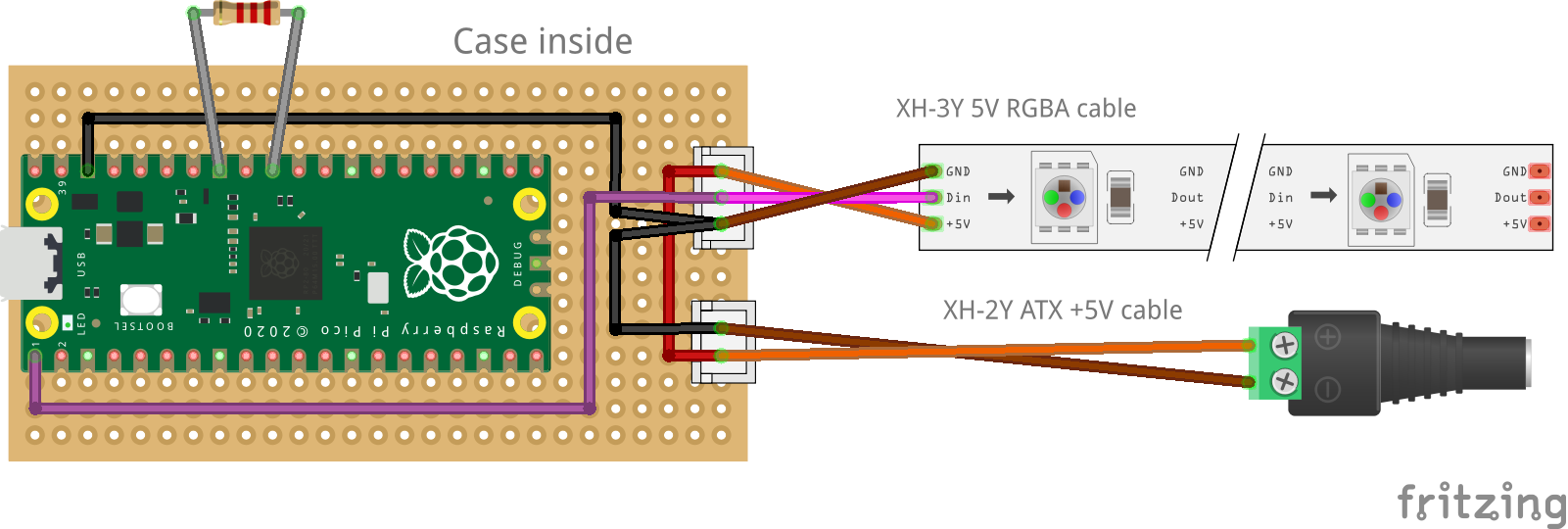
Using
Pico must be flashed with the appropriate firmware from releases.
The client software to actually control the LEDs can be downloaded from the same page, or from my repository. I have succeeded in porting all of the features from the original client to a cross-platform Rust solution that doesn't require .NET CLR.
Have fun. 😉