
Prusa INDX tool dock with magnet install tool, magnet poke holes, and optional threaded inserts
Obliczymy ostateczną cenę na podstawie wybranego pliku. Sprawdzisz ją i zaakceptujesz przed płatnością.
Zapisane na tym urządzeniu.
Informacje o modelu
- Źródło
- Printables
- Kategoria
- Prusa Parts & Upgrades
- Licencja
- Open Community License v1.1
Summary
After all the updates I should summarise what's now in this model:
A minor remix of Prusa's original Tool Dock model to include magnet poke holes. As well as this simple remix, all the other STLs in this model include these holes.
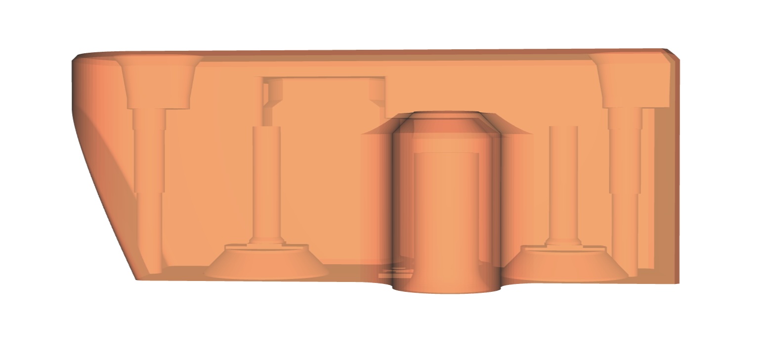
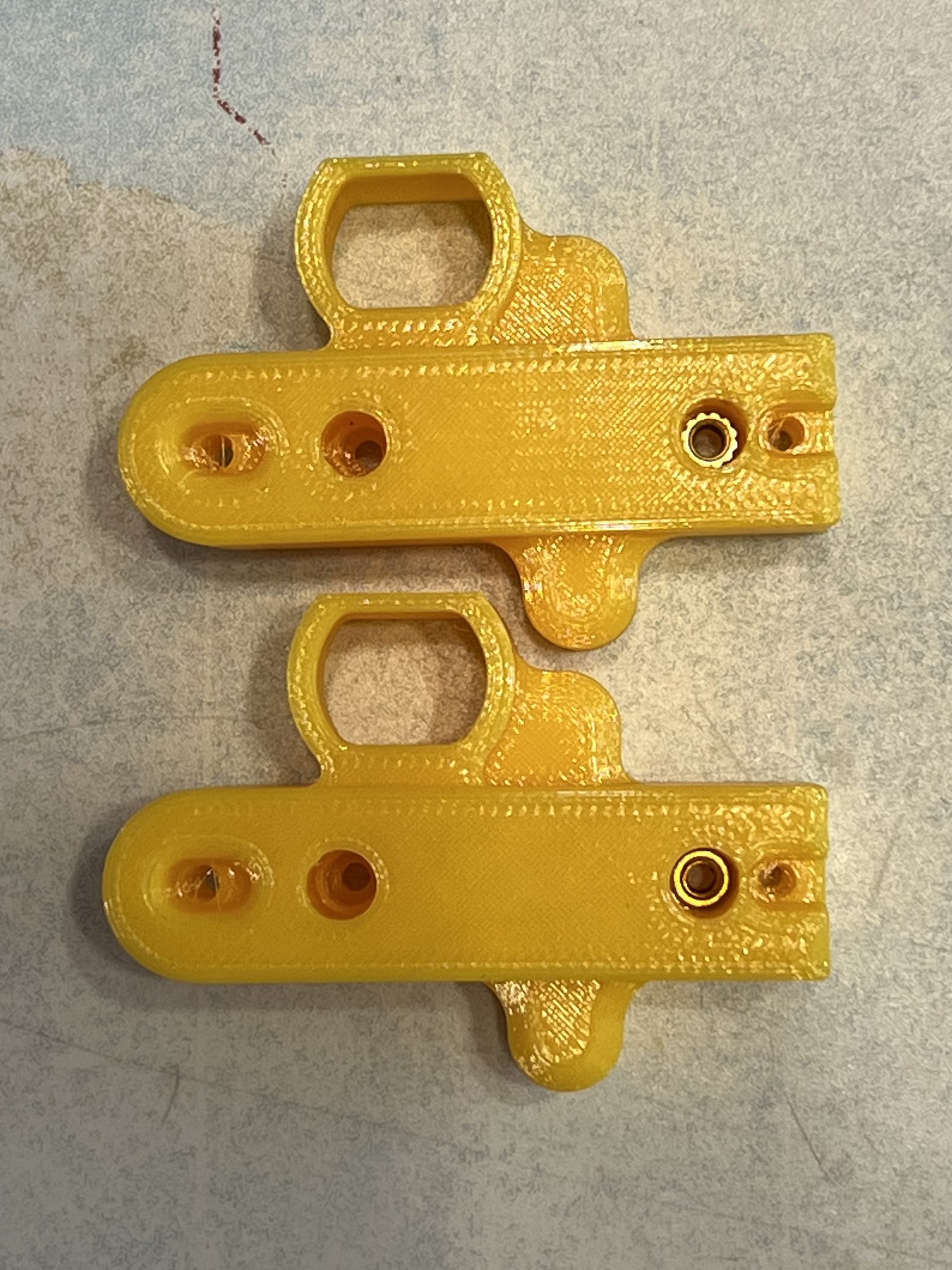
An STL that allows screw-in inserts to be inserted from the front plate side of the tool dock
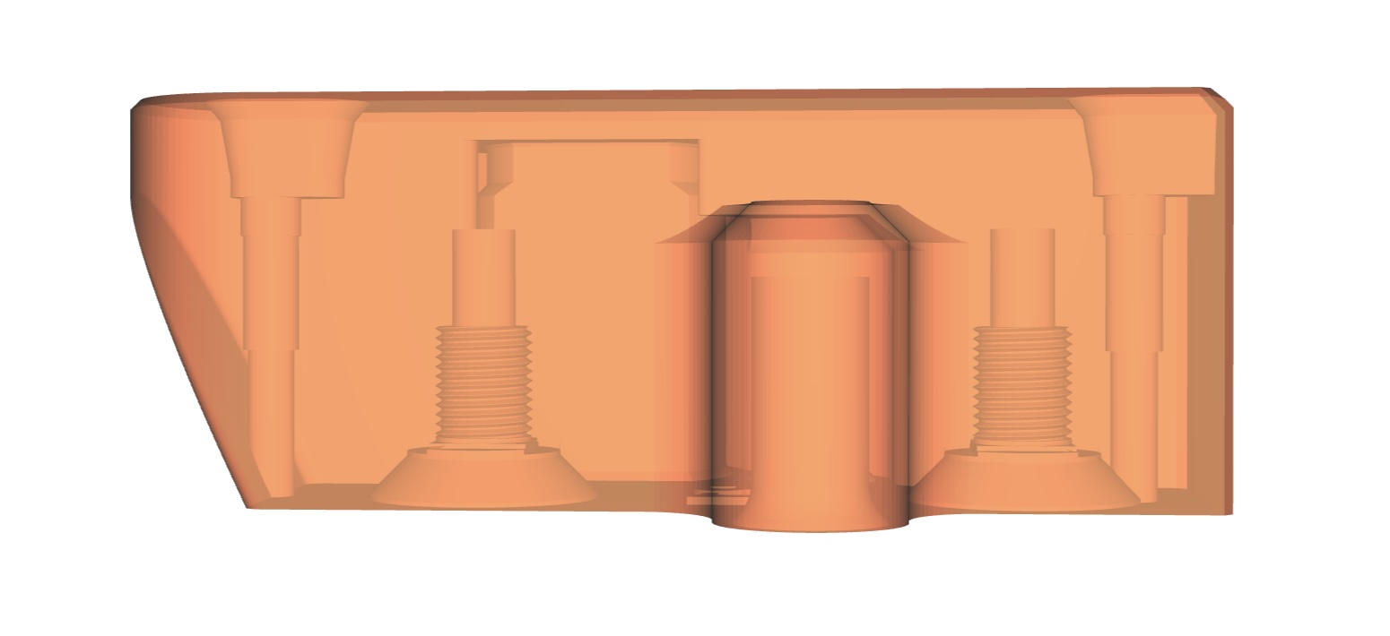
An STL that allows screw-in inserts to be inserted from the tool side of the tool dock
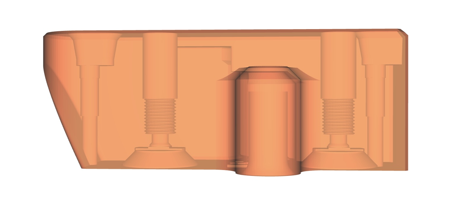
An STL that allows heatset inserts to be inserted from the tool side of the tool dock
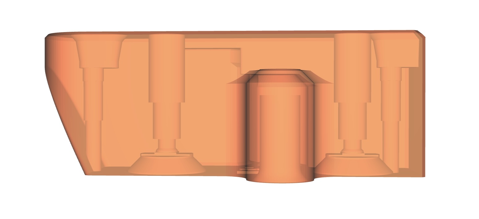
Two halves of a magnet assembly tool to aid with the insertion of the magnets. Two versions are supplied: One to suit generic 3mm dia x 8mm rod magnets, and one to suit 2.8mm dia magnets, based on a Discord report of a measurement on one of the original magnets recovered from a broken original tool dock.
Update 19JUL26
Following feedback from user Hachiro, who posted that printing both the tool dock and the assembly tool in ASA leads to a very tight fit between the two, I have now done the same and confirmed the problem. My own testing was with ASA tool docks and a PETG assembly tool, and I think the slight shrinkage of the ASA tool dock disguised the fact that my modelled clearance gap wasn't sufficient. I have increased the clearance gap to solve this. The top has a little more clearance than the base, because its alignment is less critical.
Update 16JUL26
At the suggestion of Tommy_Prusa3D, no less, I've added models that allow the threaded inserts to be inserted from the tool side of the tool dock, rather than the more obvious front plate side. See 'Tool-side Threaded Inserts' description below. I promise I won't ever say 'final salvo' again :-)
Update 15JUL26
After a report from someone who's recovered the Bondtech supplied magnets from the original tool docks, I've made a couple of tweaks to the assembly tool. It seems that the Bondtech magnets might have a slightly smaller diameter - 2.8mm, versus the 3.0mm of the ones I purchased separately.
Update 13JUL26
I added a top piece for the magnet helper tool, so that the force needed to press the magnets in is applied only to the two halves of the helper tool - the tool dock inside is protected.
Update: 12JUL26
The 3mm dia x 8mm magnets are very tight in the modelled holes. They need to be to guarantee that they won't pull out when the tool is pulled away from the tool dock. But it makes their installation a bit tricky, so I've made a small tool that can help with this. See magnet_helper_tool_base.stl and magnet_helper_tool_top.stl, and the write-up below.
Update: 03JUL26
My final salvo in the battle of the Prusa INDX tool holders!
I modified the screw holes to take screw-in threaded inserts. Other models have already offered the more widely used heat-set threaded inserts, which require a soldering iron to push them in, but I've come to prefer the screw-in variety as it's much harder to get the alignment wrong than with the heat-set insert. I modelled a thread to suit M3 screw-in inserts with an overall length of 6mm and an external M5 thread (0.5mm pitch). I used zinc-plated carbon steel inserts, which are the same ones I've used in my belt-tensioner-pulley remix. My model includes the same type of 'suspended hole helpers' that Prusa's original model uses, adjusted to suit the diameter of the inserts, such that supports aren't needed on the flats of the countersunk holes.
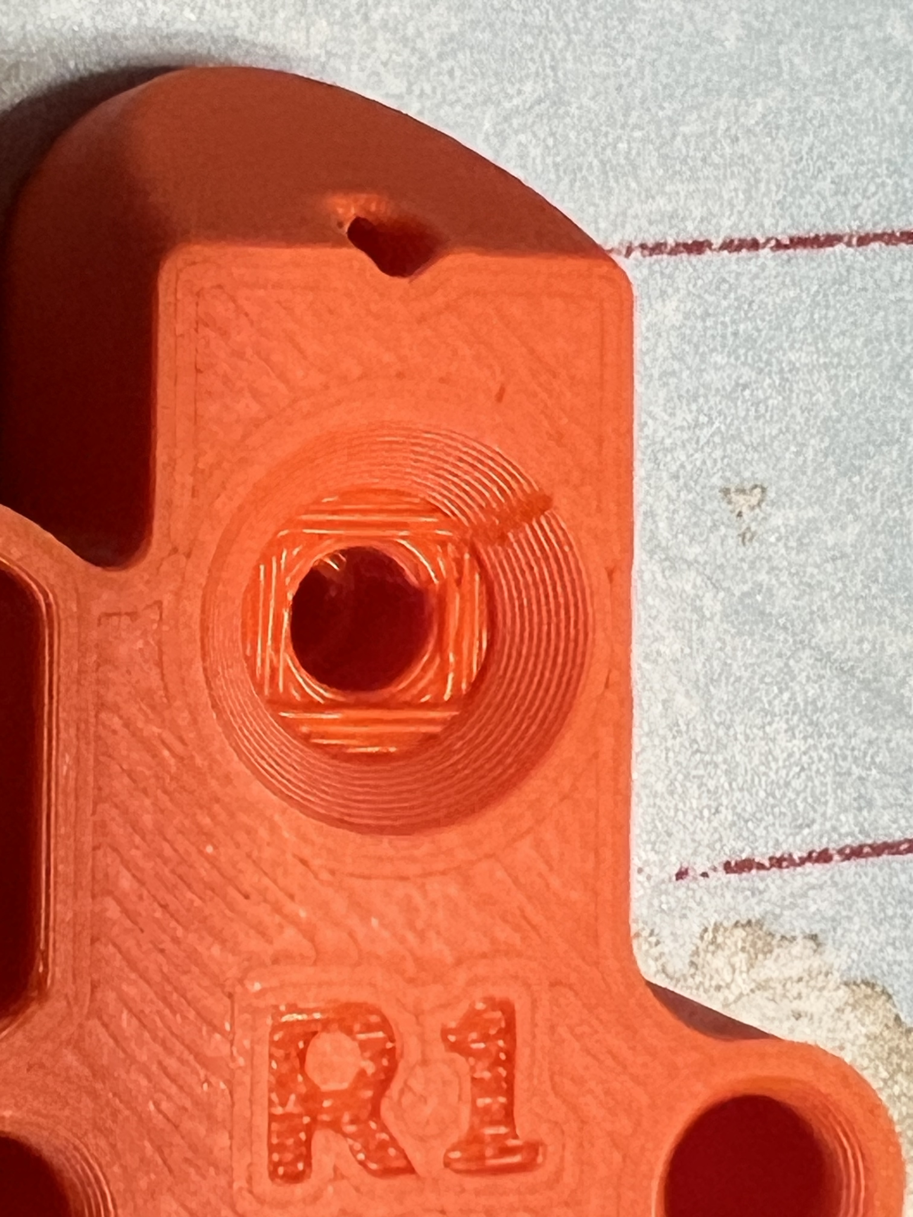
I widened the magnet poke holes by a tiny amount so that the stiffer 2mm hex key can be used.
I've left the original STL here, but if you want a version without the insert holes I've also uploaded an STL with only the slightly wider poke holes.
Description
The kit-supplied tool holders have magnets inserted to hold the INDX nozzles in place when they're docked. There have been reports that some tool holders have the magnets inserted the wrong way, such that they repel rather than attract the nozzles. If you print replacements, either because of this fault or because you want the tool holders in a different colour or material, you're going to need to insert the magnets yourself. You can either butcher the original tool holders to gain access to the 3mm dia x 8mm rod magnets, or you can source your own - 2 per tool holder.
Whilst it should be simple to check the magnet polarity before insertion, if you need to remove the magnets to correct the polarity or to reuse them in a different print, you'll need a way to push them out without destroying the tool holder. This model includes a 2.3mm (now updated to 2.4mm) diameter hole so that you can insert a 1.5mm (now 2mm) Allen/hex key, better yet, a 2mm drift/punch, to push the magnets out.
Threaded Inserts
If you're unfamiliar with the screw-in inserts and are concerned that you might need a special tool to insert them, there's a simple makeshift way to insert them without any other tools - you need only a spare insert and an M3x8 screw.
Screw the spare insert onto the screw, with the wider, non-tapered end towards the screw head, and the slotted tapered end towards the end of the screw. I previously thought it best to put the slotted end towards the head, so that it could be used to unscrew the insert if it jammed in the piece, but I now think that the tapered end is less likely to jam in the first place because of the taper and the reduced contact area.
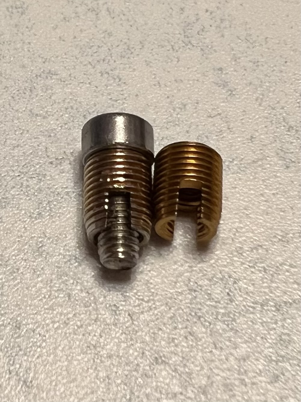
Next, screw the main insert onto the end of the screw, with the slotted tapered end furthest from the head. The slot and the taper are part of the thread-cutting design.
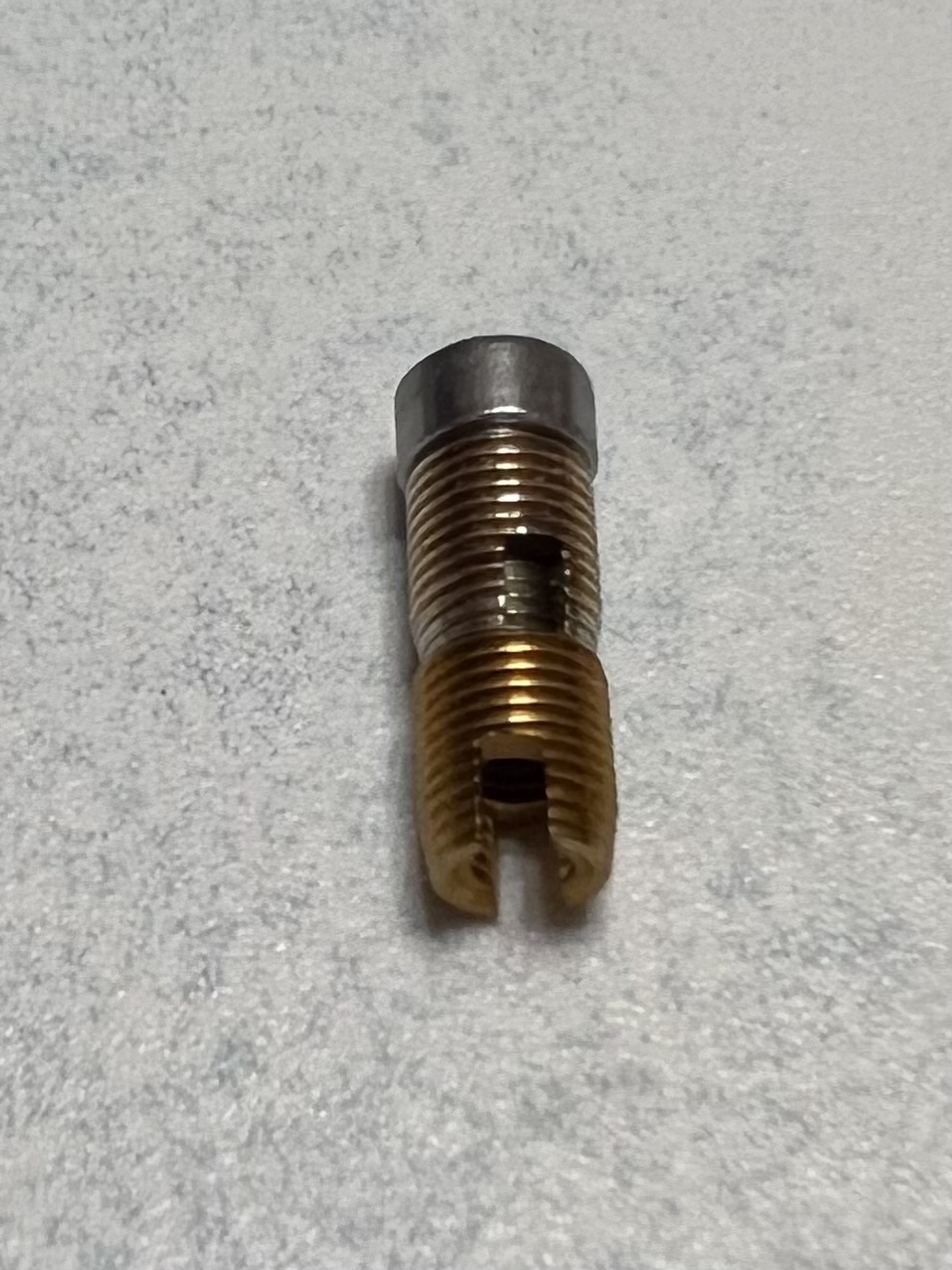
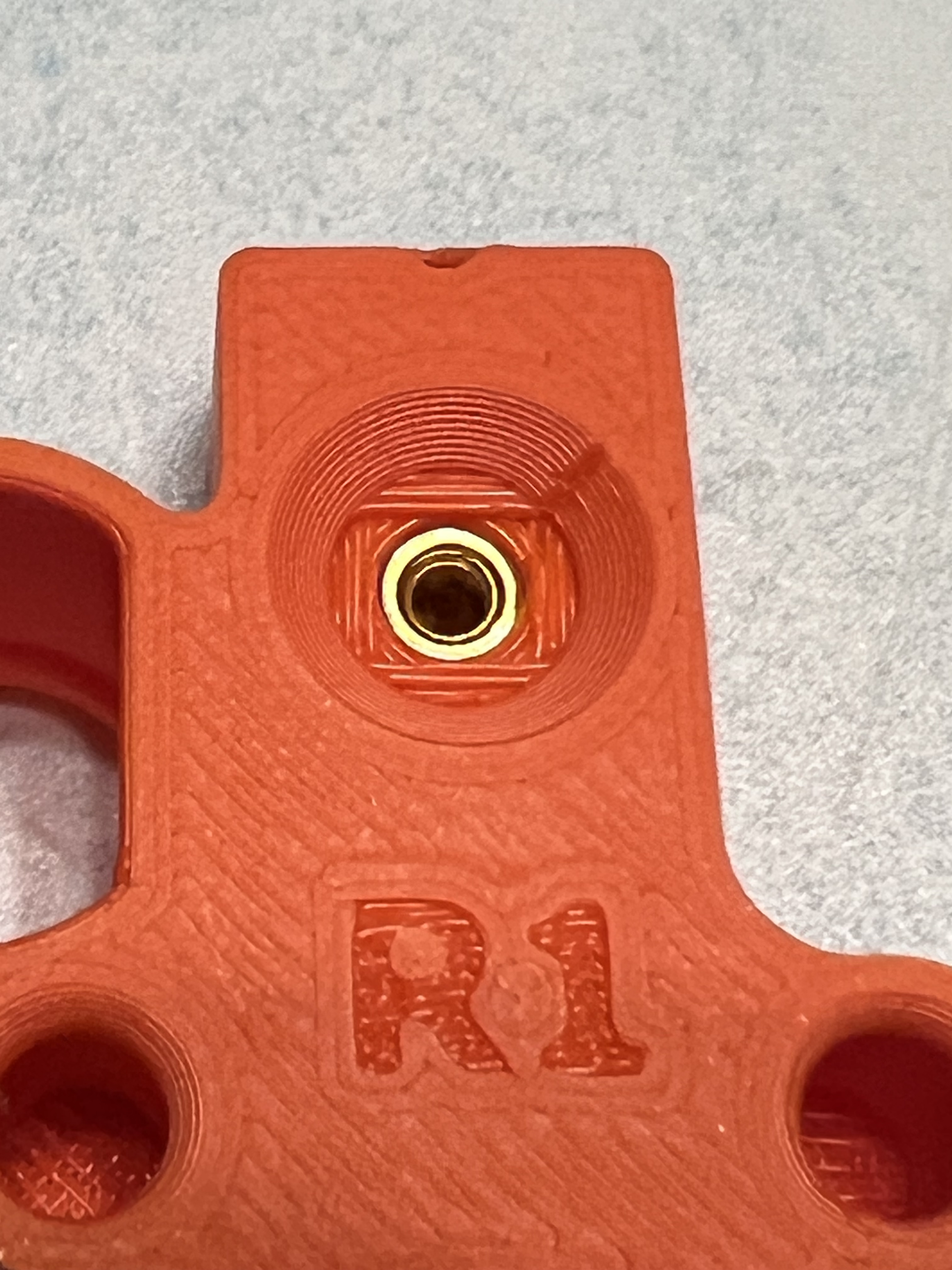
Then insert the tapered end into the threaded hole in the printed part and use a normal screwdriver to screw the whole assembly into the hole. The hole is sized to suit a 6mm long insert and it will stop turning once it reaches the end of the hole. Unscrew the makeshift insertion tool - screw+spare insert.
Tool-side Threaded Inserts
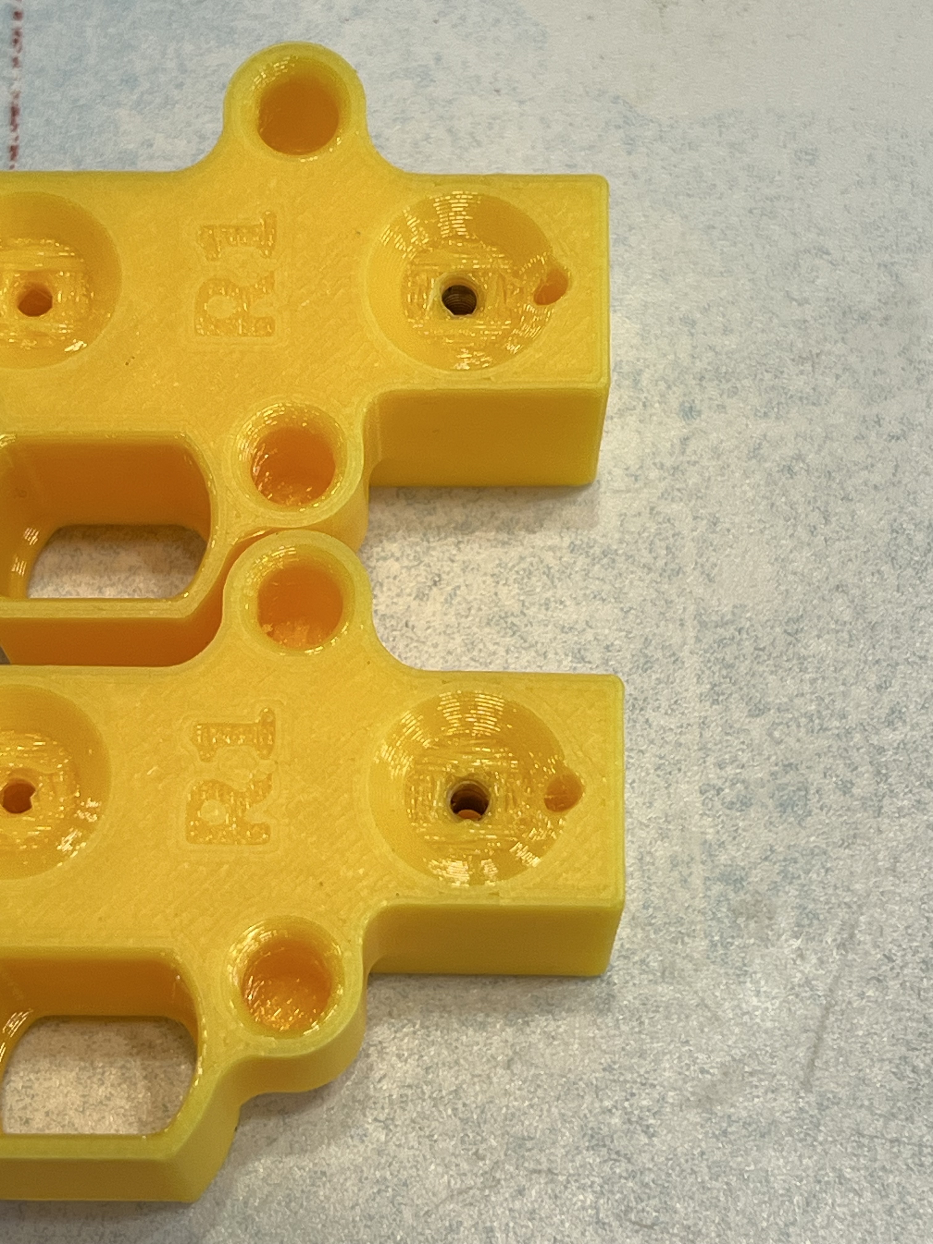
Threaded inserts that are inserted from the front plate side of the tool dock should provide plenty of pull-out resistance against the magnetic force of the nozzle tools - likely at least as much as Prusa's original design in which the screws cut their own thread into the plastic. Nevertheless, a little extra pull-out resistance can't hurt. So I've added a couple of models in which the inserts are inserted from the tool side of the tool dock, leaving ~1.5-2mm of plastic shoulder for the inserts to pull against. I've left the diameter of the hole in that shoulder the same as the original part, so it'll take a little effort to start the screw, but it will of course provide a little of the 'nyloc' effect to stop the loosened screw shaking loose.
I've provided two models: one for screw-in inserts and one for heatset inserts. In both cases I've made the hole that they drop into wide enough for them to drop in easily, before narrowing down to a screw thread or a plain cylinder depending on the model. In these models the length of the threaded insert is much less critical, since it will stop when it reaches the shoulder, with plenty of space above.
The screw-in insert is very simple to use. The heatset insert will require a very steady hand since the soldering iron tip or the insertion tool will be a close fit. I daren't make the holes any larger since one of them is close to the magnet hole and I didn't want to thin the separating wall too much. For my test I used a cap head screw in the insert so that the soldering iron tip didn't have to push in so far.
Tip: Once the inserts are in, run a long M3 screw all the way through from the tool side, to clear any plastic swarf in the shoulder section.
Photos: Heatset above, screw-in below.
The Magnet Helper Tool
See the update at the end of this section regarding the Bondtech 2.8mm diameter magnets.
The 3mm dia x 8mm rod magnets are a very tight fit in the tool dock magnet holes. This is so that they don't pull out when the tool is pulled out of the dock. This makes them quite difficult to install into the tool dock part, so I have made a helper tool. The holes in Prusa's original tool dock have a 2mm deep 'starter' hole, to help locate the magnet, and then the magnet needs to be pressed home into the main hole until the top of the magnet is flush with the top of the recess. However, even the starter hole is a tight fit, and it can be difficult to get the magnet started in this hole.
This helper tool aims to assist in initially loading the magnets into the starter holes, and then to provide a convenient means of pressing the magnets all the way into the hole.
Start by screwing a couple of M3x8 socket head screws into the helper tool base from below - don't over tighten since they are only screwing into plastic. Screw them in until the heads are flush with the underside of the helper tool.
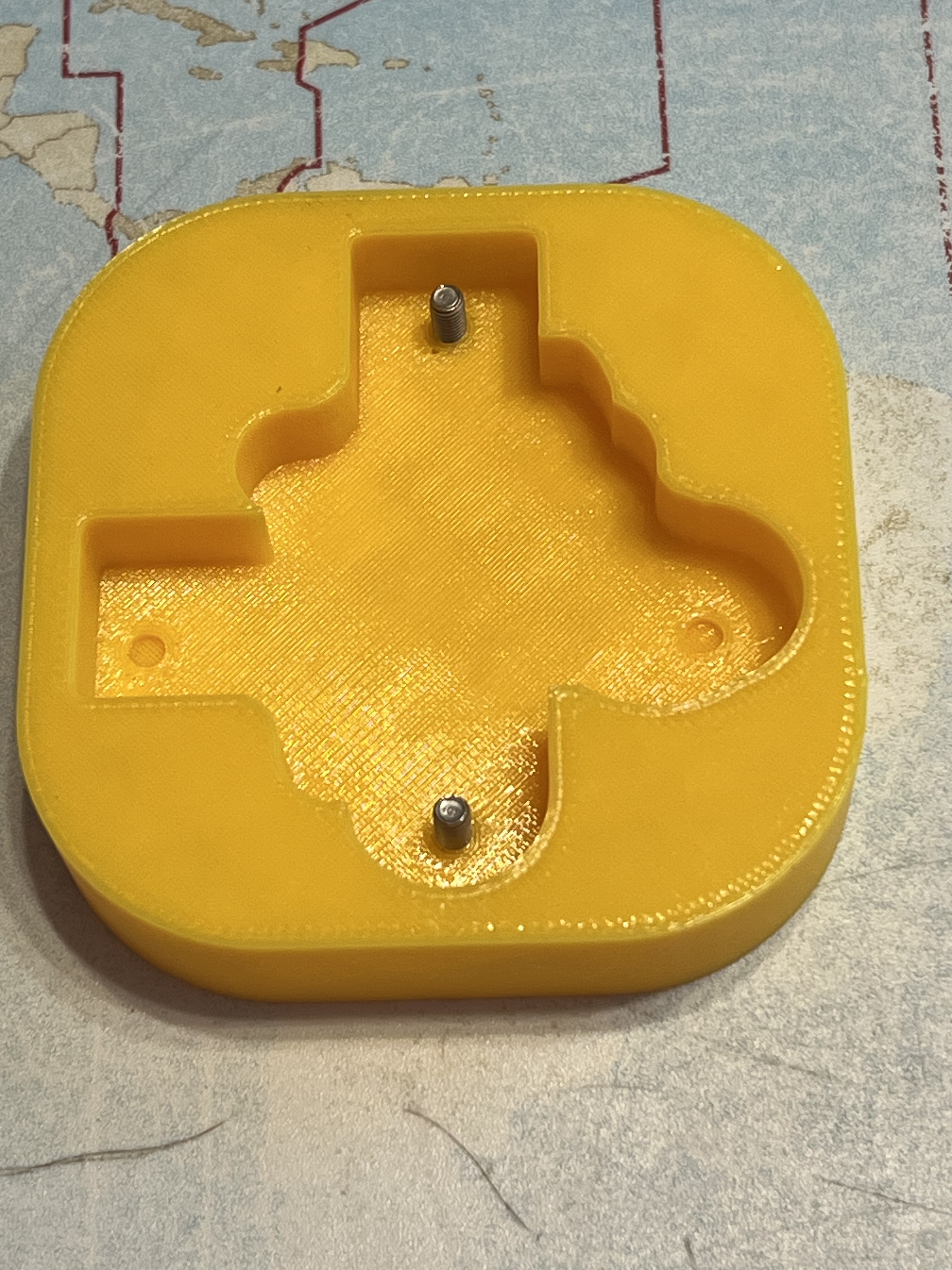
Now identify the correct orientation of the magnets - hold them against the pins on one of the tools (assuming all the tools have their pins correctly oriented - you may want to double check this). In one orientation the magnet will repel the tool and in the other it will attract the tool. Find the orientation in which the magnet is attracted to the end of the pin, and let it affix to the end of the pin. Mark the free end with a marker pen. The marked free end is the end that has to be pushed into the tool dock first, so insert the magnet into the recess in the helper tool, unmarked end first, so that the marked end points upwards. Note that the recess isn't deep - it can't be, because the dock needs enough of the magnet protruding in order to be able to 'grab' the magnet. So locate the magnet in the recess - pliers or tweezers may help - then push it into the recess so that it stays put.
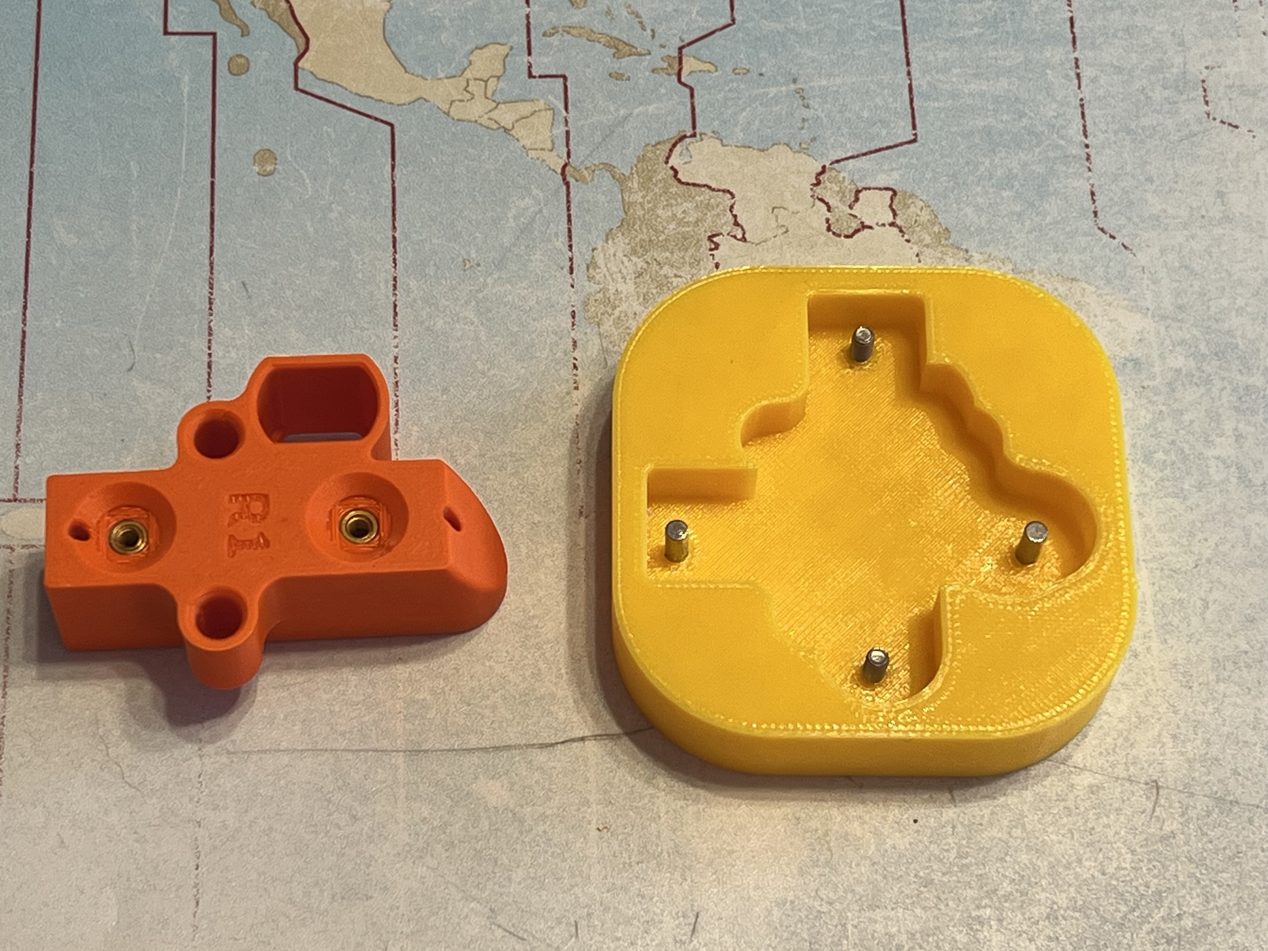
Now locate the tool dock over the magnets and push it down firmly into the recess in the helper tool base. Hand pressure should be enough. When you remove the tool dock the magnets should come out of the helper tool and stay in the starter holes in the tool dock.
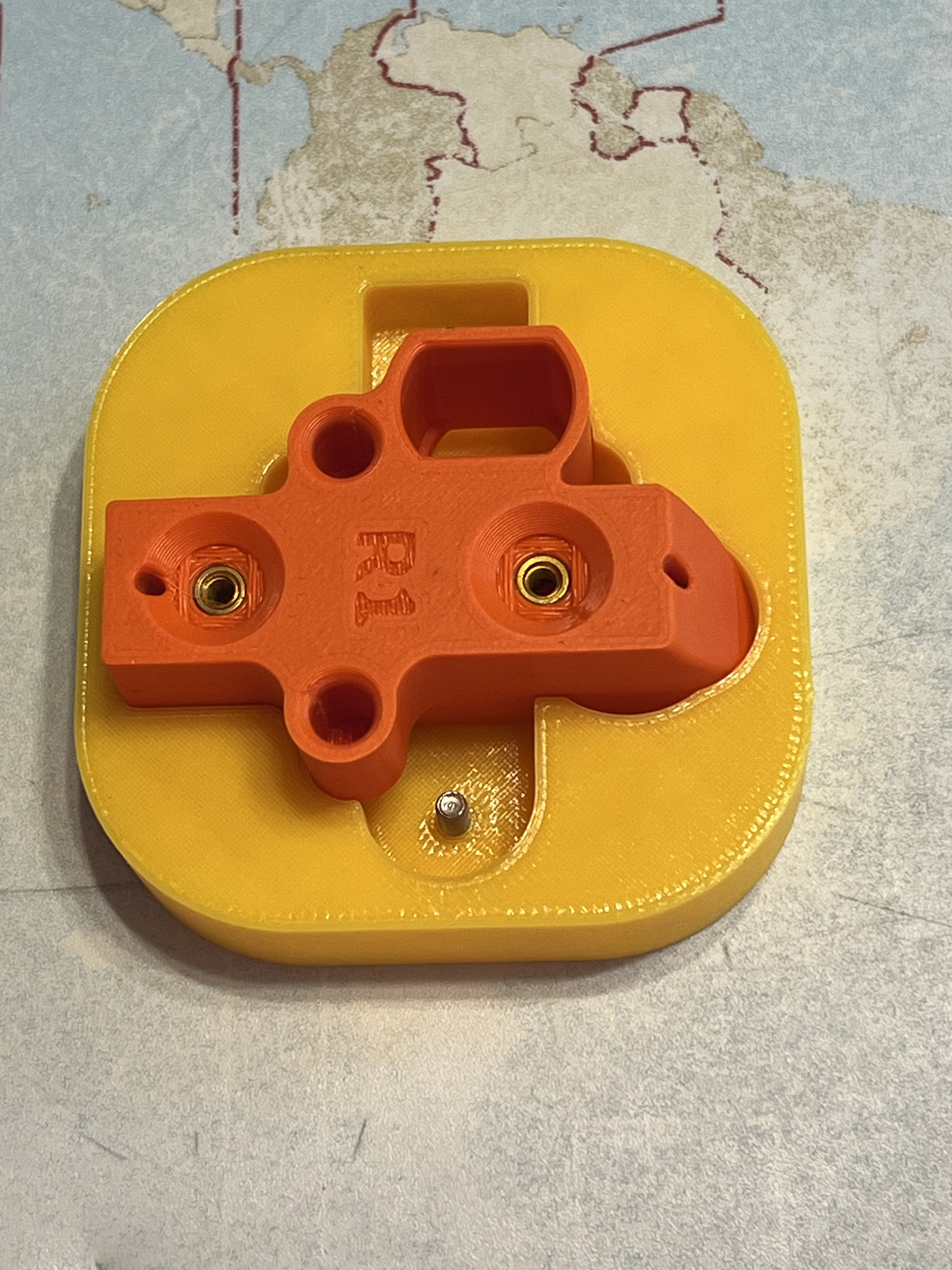
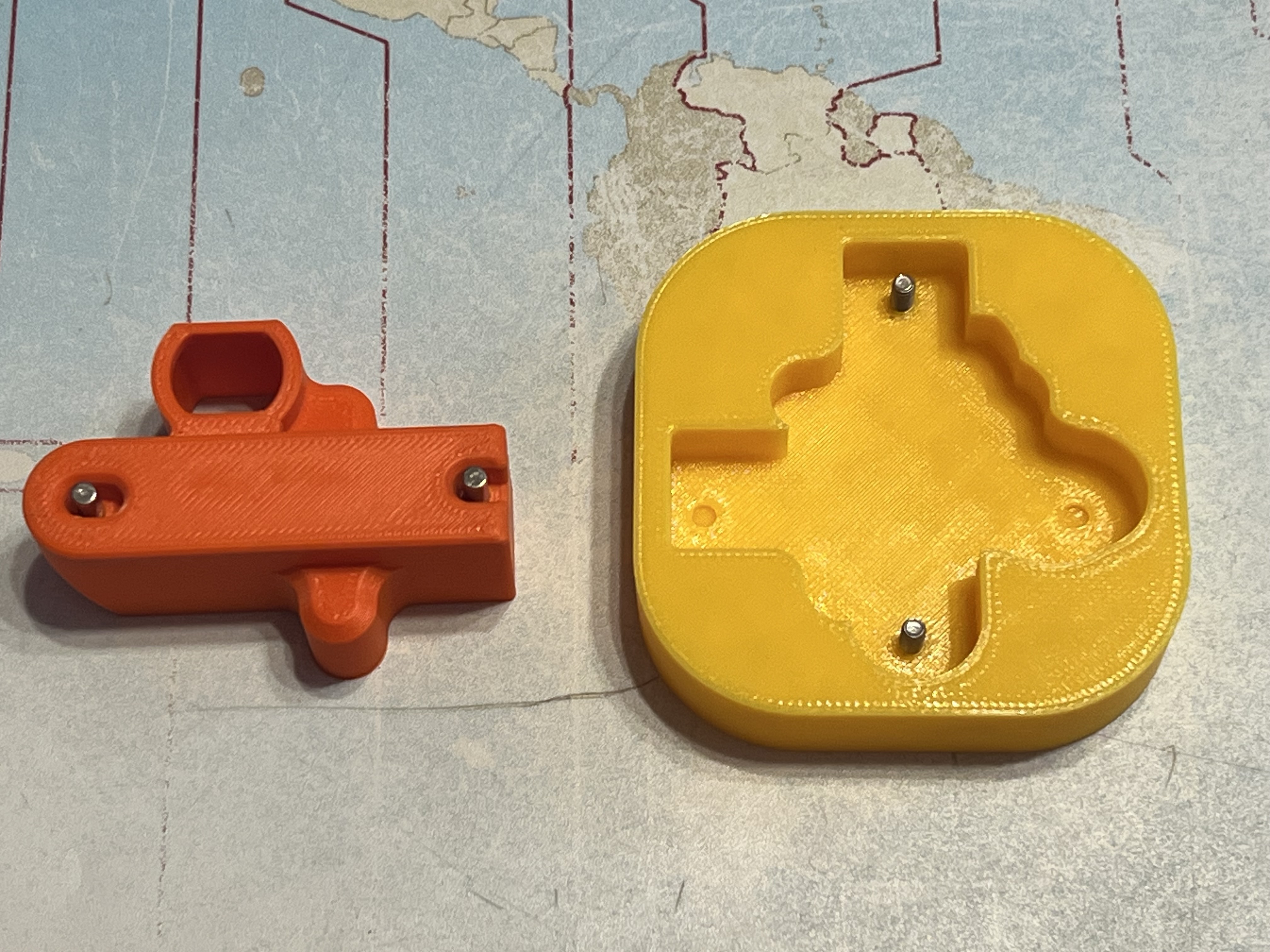
Now locate the dock with the started magnets over the two M3 screws and insert it into the corresponding recess in the helper tool base.
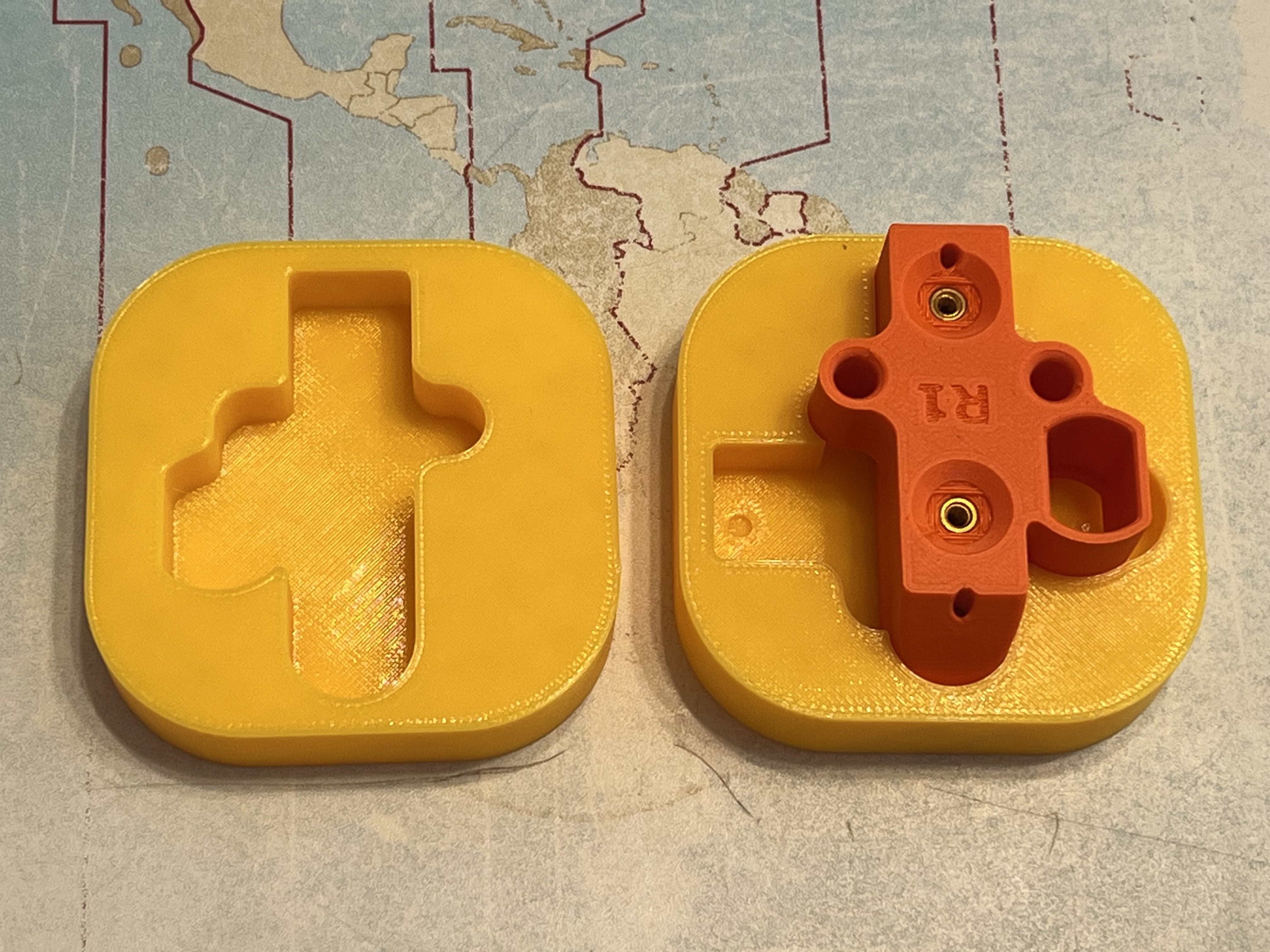
Place the magnet_helper_tool_top on top of the tool dock and magnet_helper_tool_base.
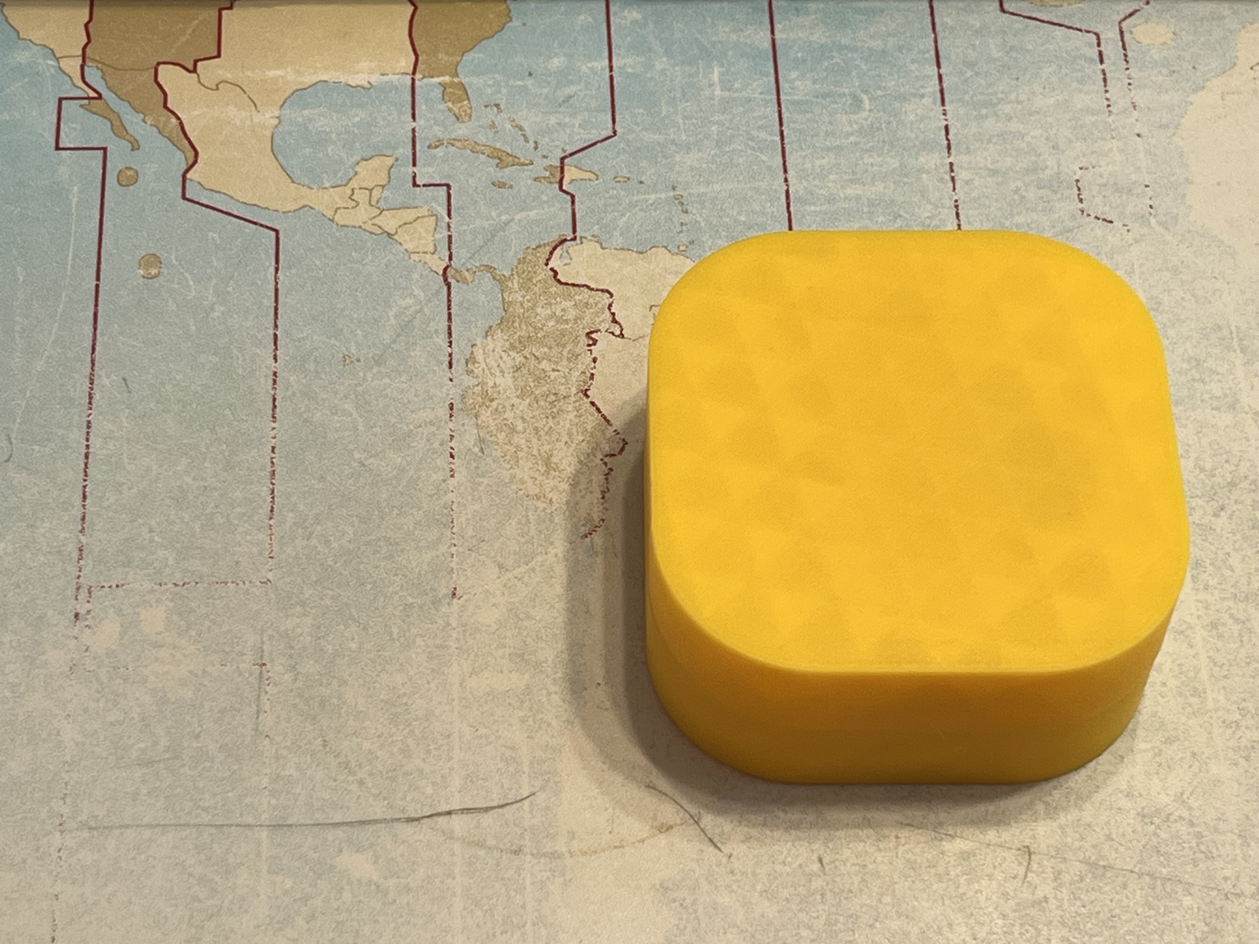
Now you can apply even pressure to push the tool dock down into the helper tool so that the magnets are pressed fully into the holes by the screws. This will require a lot of force - probably more than you can apply by hand. You could use a vice, but I've had success simply by standing on the piece with my heel, with the magnet_helper_tool_top uppermost and the magnet_helper_tool_base on a hard surface so that the screw heads are not pushed out of the helper tool.
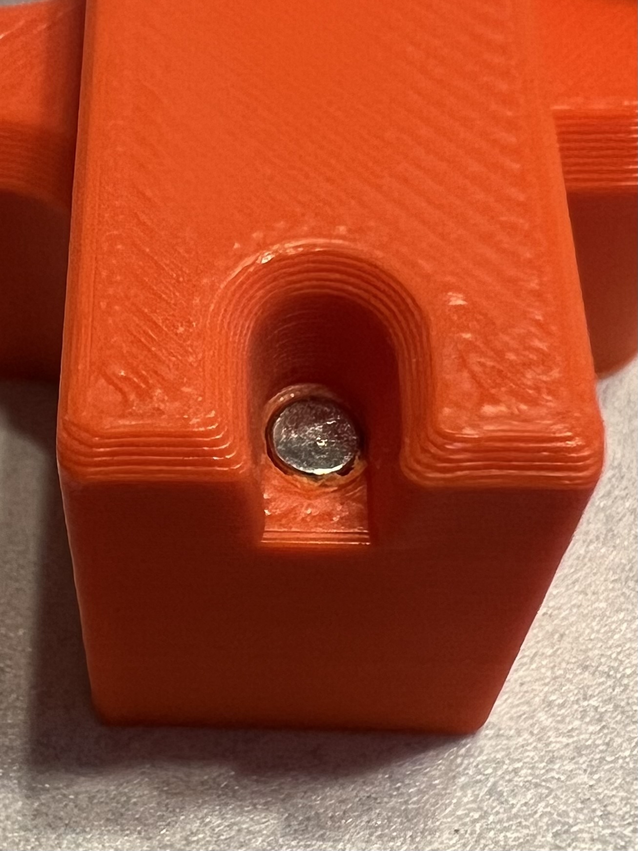
Test that the nozzle tool is attracted to and held by the tool dock. If you make a mistake with the magnet orientation, the magnets can be removed using the poke holes on the reverse of the tool dock, but you will likely need a 2mm drift and a hammer, with the tool dock placed on e.g. a carpeted surface so that there's room for the magnets to be pushed out.
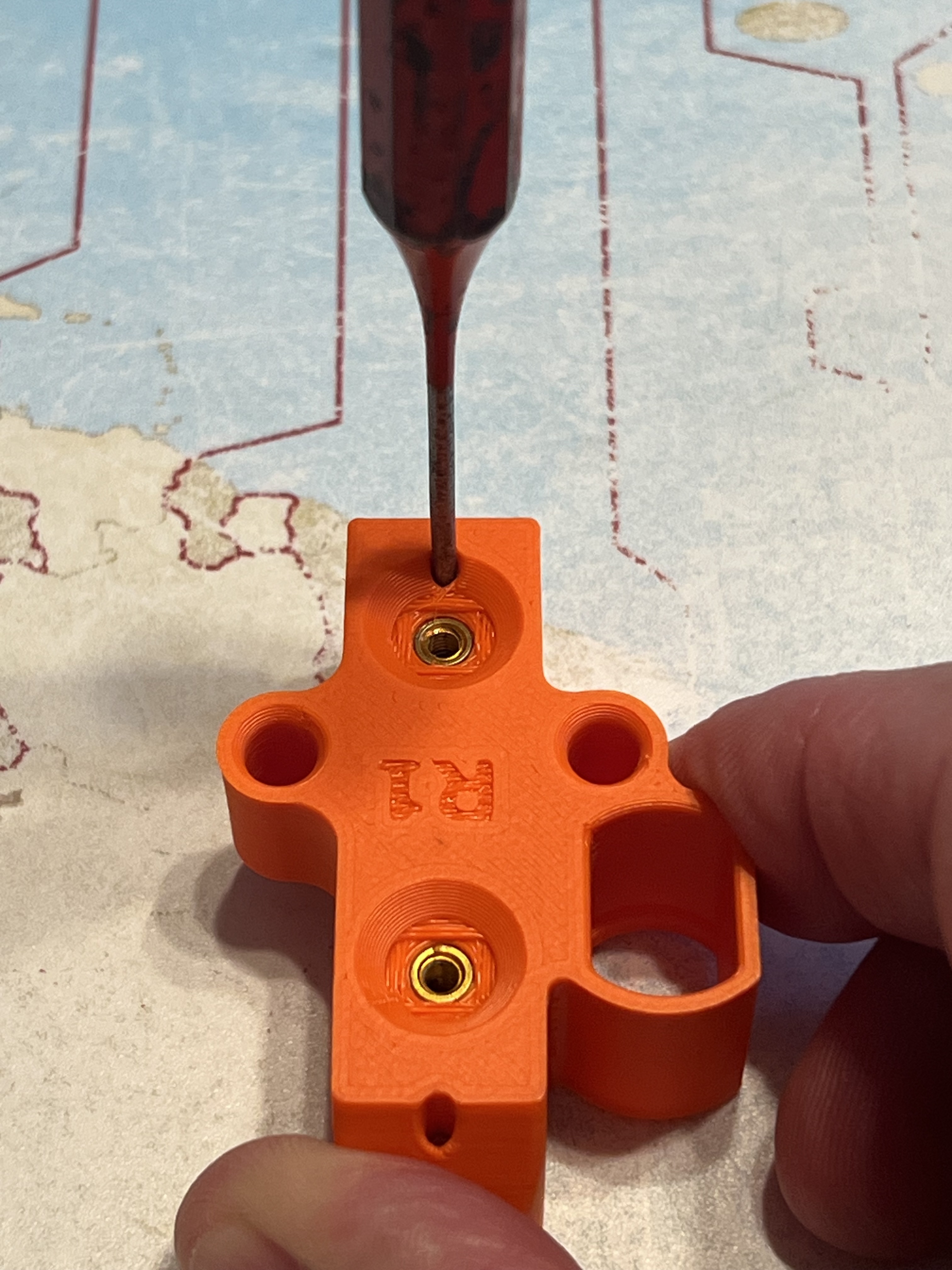
N.B. Based on a report from someone who has recovered the magnets from the supplied tool docks, it seems that their diameter of 2.8mm is slightly less than my original model assumed. This meant that the magnets didn't stay upright in the modelled recesses during the first step. I've therefore made a couple of changes to the base part.
I've added a small support beside the recess, so that the magnet can rest against this to keep it upright.
I've added a version of the model that assumes 2.8mm diameter magnets. Both the 2.8mm and 3.0mm versions are in the downloadable files.
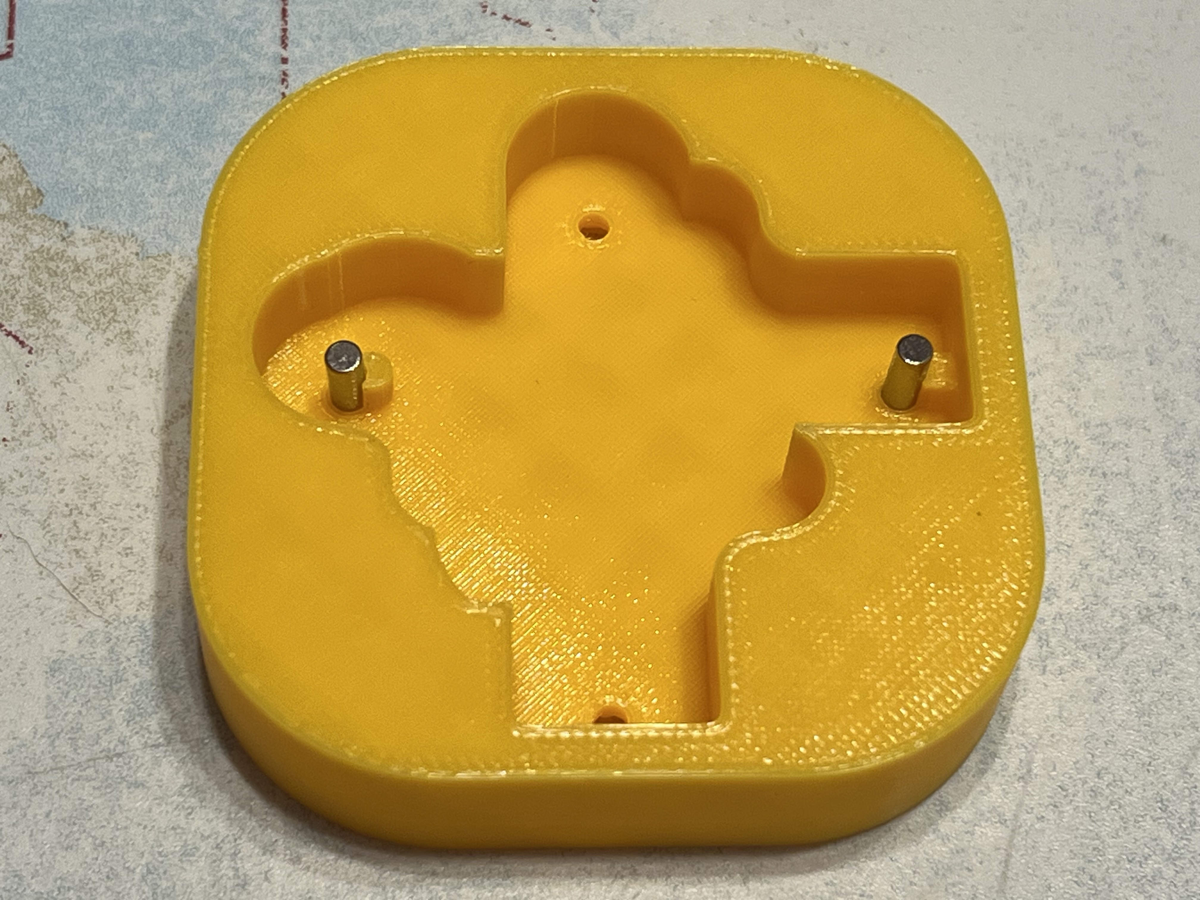
The same person who reported the smaller magnets ingeniously suggested using a magnet on the underside of the tool base to hold the magnets in place temporarily. Obviously, watch out for the correct polarity, to avoid your rod magnets flipping the wrong way up, but otherwise this seems like a neat idea.
Magnet Helper Tool Print parameters:
I printed my magnet helper tool parts in PETG, with the 0.2mm SPEED profile, modified to use 15% Cubic infill. The resulting parts easily took my weight when pressing the magnets in.
Print both halves in the supplied orientation. The recesses for the M3x8 screws have 'suspended hole helpers' included in the model, so no supports are necessary.
Caveat:
Note that this model was created before I've received my FE INDX conversion kit, and is based on reports in Bondtech's Prusa CORE One Discord channel. The magnet insertion instructions haven't been checked with the actual nozzle tools, so use your own judgement.