
Models of Marcel Duchamp's L.H.O.O.Q. by williamCromar: Color Separation Deep-Dive
Obliczymy ostateczną cenę na podstawie wybranego pliku. Sprawdzisz ją i zaakceptujesz przed płatnością.
Zapisane na tym urządzeniu.
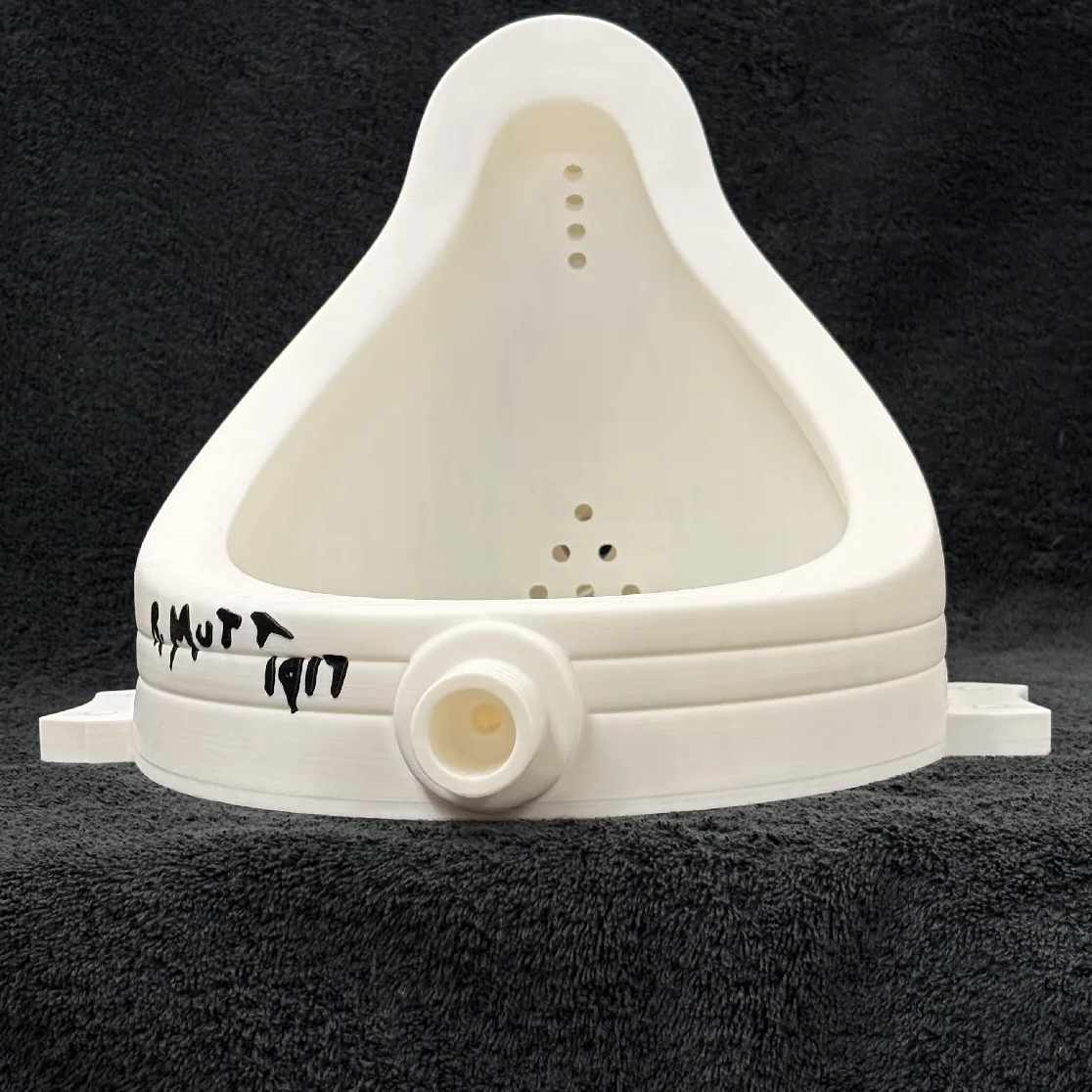
Club-exclusive experimental geometric variants from Prêt à Faire, supported by Penn State Abington. CC BY-NC-SA 4.0.2
- Ocena
- 0 / 5
- Polubienia
- 0
- Wydruki
- 0
- Wyświetlenia
- 13
- Oceny
- 0
Aktualizacja u źródła:
Informacje o modelu
- Źródło
- Printables
- Kategoria
- Sculptures
This premium component set features advanced developmental variations expanding upon the open-access reference collection Prêt à Faire: Printable Readymade Models. Accessible under a distinct commercial framework, these deluxe file configurations—alongside official Exhibition Master Proof prints—function as active components of the project's broader institutional and marketplace critique.
1 | Concept & Provenance
This collection compiles specialized geometric data sets and vector separations engineered to facilitate custom spot-color lithophane development for Model of Marcel Duchamp's L.H.O.O.Q. by williamCromar (specifically referencing the 1919 and 1930 historical variants). This release grants Club members access to the exact workflow used to translate image files into fully 3D-printable multi-layered color matrices.
While platforms like ItsLitho traditionally recommend printing a color graphic onto standard paper backing, that method separates conventional 2D printing from true digital fabrication. Duchamp famously questioned these rigid boundaries—between art and ordinary objects, originals and reproductions, handcrafted work and manufacturing. Extending that inquiry into the fabrication process itself means generating both the values of the lithophane and its transmissive color layers entirely within a 3D printing environment.
By utilizing a unified process, the work becomes a wholly printed object rather than a hybrid of paper and plastic. The goal isn't material purity, but image production consistency: every visible component is generated from the exact same digital workflow, while the LED hardware serves strictly as an external display apparatus.
Why not CMY?
Standard color lithophane platforms like MakerWorld typically employ CMY channel separation to simulate the continuous-tone behavior of traditional color printing. While impressive, these systems offer very limited control over saturation and tonal gradation, often producing a crude approximation of subtle gradients.
Rather than pursuing an imperfect simulation of CMY reproduction, I adopted a spot-color strategy using raw image data as a guide. By modeling each color zone as a discrete printed region, this workflow provides precise control over the final image while avoiding the limitations inherent in CMY-filament optical blending. The result is an intentional translation of the image into a form native to 3D printing.
This approach directly aligns with the project's broader commitment to open digital fabrication. Platforms like MakerWorld provide valuable sharing networks, but their walled-garden structures raise questions about access, ownership, and control. For a project centered on the digital readymade, unrestricted file access is conceptually vital. The asset is not merely downloadable; it is reproducible, transferable, and remixable outside the boundaries of any single platform.
2 | The Workflow
To support an instructional research initiative funded by a faculty grant from Penn State Abington, I developed a step-by-step translation process to convert 2D color images into clean 3D geometry:
Generate Source Files: Export the baseline normal maps, color layouts, and STL data from your chosen rendering engine.
Analyze Image Contrast: Observe how edges and contrast shift to inform your custom color separation boundaries.
Plan Separations for Optical Mixing: By treating a 3D printer like an analog multi-stage halftone layering system, you can build a custom 2-stop optical-density matrix. Stacking identical translucent layers increases the optical path length (doubling the pigment density), while backing a color with clear filament dilutes the color saturation by allowing light transmission through that specific depth. Working with 3 translucent colors, 1 transparent color, and an orange balancing tone to offset cool LED blue light casts, we generate a highly predictable 9-tone matrix:
Target Tone | Brand & Formulation |
|---|---|
Gray (#A5A39A) | Bambu Lab Translucent Gray PETG |
Light Warm (#D3A279) | Push Plastic Translucent Amber PETG |
Dark Brown (#6B4F39) | Anycubic Translucent Brown PETG |
Transparent | Prusament Clear PETG |
Orange for paper-white | Bambu Lab Translucent Orange PETG |
With 2 vertical layers and 3 distinct spot-tone filaments plus a 100% clear filament, the matrix will yield these exact transmissive behaviors:
Layer 1 | Layer 2 | Resulting Optical Effect |
|---|---|---|
Gray | Clear | Light Neutral Gray: Desaturated midtone; smooth values. |
Gray | Gray | Deep Gray: Maximum density; rich shadows. |
Light Warm | Clear | Pale Ivory/Cream: Soft, highly translucent warmth. |
Light Warm | Light Warm | Rich Amber/Tan: Saturated midtone warmth. |
Dark Brown | Clear | Medium Earthy Ochre: Balanced brown tone. |
Dark Brown | Dark Brown | Deep Chocolate Brown: Maximum shadow value. |
Gray | Light Warm | Warm Muted Gray: Muted tone ideal for neutral highlights. |
Gray | Dark Brown | Dark Sepia / Umber: Moody, deep analog print tone. |
Light Warm | Dark Brown | Warm Chestnut: Highly saturated dark earth tone. |

Prepare the images. Open the images in an image editor and apply a slight blur to reduce unnecessary detail.
Vectorize the images. Import the images into a vector illustration program and apply image tracing. Trace each using approximately 4–6 tonal or color levels, depending on the image complexity.
Simplify the vector paths. Reduce unnecessary nodes and irregular edges to produce cleaner geometry that is easier to model and prints more reliably.
Apply the 9-tone color logic to the fills. Analyze the fill of each area and assign a corresponding tone from the matrix above.
Create 2 layer separation files. Darkest areas will have double layers of the same color, while intermediate mixes will have a combination of 2. Lighter areas will have one color layer and one transparent layer. The paper-white areas have one orange layer and one transparent layer.
Separate the traced regions. Keep each traced color or tonal region as a separate vector object, but leave all adjacent regions together in a single SVG. Each SVG will ultimately become one printable layer. You may need to eliminate adjacent objects where borders don't fully align, so that the CAD file can interpret them correctly.
Representative color separations for the 1919 and 1930 editions are shown below.
1919 color separation study
 Historical Original |  B+W |  ItsLitho Color |
|---|---|---|
 My Color |  Layer 1 |  Layer 2 |
1930 color separation study
 Historical Original |  B+W |  ItsLitho Color |
|---|---|---|
 My Color |  Layer 1 |  Layer 2 |
Now, we translate from image to object:
Create printable solids. Import each SVG into a CAD program as a sketch, and extrude every enclosed region to the thickness of a single printed layer (typically 0.15 mm or 0.20 mm). Each region becomes its own solid body, but all of the bodies are exported together as a single STL.
Build the color layers. Color regions may be printed as either single-layer parts or paired two-layer stacks. The slicer currently cannot assign separate colors to stacks thicker than two layers.
Export the finished models. Save the color layers as STL files.
Finally, we print:
Prepare for printing. Import the STLs into your slicer. For the color layers, use the slicer's paint-on color tool in Smart Fill mode. Because each color region is already a separate solid within the STL, the slicer recognizes each as a distinct paintable region, allowing filament colors to be assigned with a single click.
Print the components. Although paired color layers are more robust, I found that even single-layer color prints release from the build plate intact.
Assemble the lithophane. In the finished construction, the lithophane forms the front face and the color layers sit behind it.
2 | The Files
You'll find the following files to download and experiment with:
A lithophane test strip. This handy file steps up in 0.15 increments to test the filament color and transparency before you commit to the print. It can be non-uniformly scaled to 0.2 or a double-height layer depending on your needs.

Lithophane STL files. The 1919 and 1930 versions each have an STL file for a monochromatic lithophane. In the case of the 1930 version, that file is quite robust, so you'll find a reduced file plus a zipped file of the original unreduced version.
COLOR STL and STEP files. These produce a single color separation layer when painted in the slicer.
3MF files. These offer the above-mentioned files preformatted for multi-material printing.
You'll also find the following support files:
SVG color separations. Use in a CAD program to experiment with your own model generation.
Legacy CMY files. The legacy files used before the spot-color solution. These files were generated at MakerWorld-Make My Lithophane. They are here simply for archiving and comparison.
Comparison of versions
I printed versions of each of the following, which are seen below for comparison:
The first iteration project, as developed using the MakerWorld CMY model
The second project, as developed using the ItsLitho color separations
The final project, using my spot-tone 9-tone matrix model.
 1919 Bambu CMY |  1919 ItsLitho Spot |  1919 My Spot |
|---|---|---|
 1930 Bambu CMY |  1930 ItsLitho Spot |  1930 My Spot |
3 | Printing and Assembly Notes
Please refer to the open-access reference listing for material recommendations and other notes:
4 | Support
Access to this file archive facilitates your active engagement with the project's broader marketplace critique. We provide direct technical support through the platform messenger to assist project participants with any advanced multi-body file manipulation, vector tracing, or optical matrix slicing inquiries. Thank you for participating in this distributed institutional inquiry.
5 | Change Log
29 JUL 2026 | Major architectural update: Transitioned the project workflow to the advanced 9-tone spot-color model. Retained legacy ItsLitho and MakerWorld CMY files within the directory for archival reference and comparison.
Disclaimer
Prêt à Faire is an autonomous artistic project, scholarly reference work, and institutional critique by williamCromar, supported by a faculty grant from Penn State Abington with fabrication assistance from the Abington MakerSpace. This project is entirely independent and maintains no formal affiliation, endorsement, or sponsorship with Association Marcel Duchamp, the Estate of Marcel Duchamp, ARS, ADAGP, or any curating museum. When referencing or sharing this work, users must maintain a clear distinction in authorship and nomenclature from the historical referent. Cite this asset as: Model of Marcel Duchamp’s [Object Name] by williamCromar. Basic models are available under a CC BY-NC-SA 4.0 license; premium tiers operate under a separate commercial framework. For full conceptual and legal text, visit https://sites.psu.edu/pretafaire/disclaimer-and-licensing/