
Low Profile CYD Pendant Case for FluidNC
Obliczymy ostateczną cenę na podstawie wybranego pliku. Sprawdzisz ją i zaakceptujesz przed płatnością.
Zapisane na tym urządzeniu.

Slim CYD pendant case with a 60 mm handwheel, three compact buttons and optional magnets for mounting.
- Ocena
- 0 / 5
- Polubienia
- 7
- Pobrania
- 11
- Wydruki
- 0
- Wyświetlenia
- 149
- Oceny
- 0
Aktualizacja u źródła:
Informacje o modelu
- Źródło
- Printables
- Kategoria
- Electronics
- Licencja
- Creative Commons — Attribution — Noncommercial — Share Alike

CYD Pendant: print, assemble and set up
I built this for my LowRider 4. It keeps the slim shape of V1 Engineering’s low-profile case and adds three compact momentary buttons below the screen, alongside a 60 mm handwheel. Choose a basic bottom shell or a shell with heat-set inserts and eight hidden magnets for magnetic mounting.
I started with CYD Pendant Case, Low Profile by V1 Engineering. I extended it by 16 mm for the buttons and changed the connector corner to take an upright Treedix breakout. FluidDial-CYD by dJOS1475 runs on this three-button pendant; FluidNC runs on the CNC controller.
The photos show my finished navy-and-cream build with the cover and handwheel knob fitted, exposed metal button nuts and FluidNC artwork. The download contains the plain models. The magnet insertion pause and resume worked on my Elegoo CC2.
Choose the parts to print

The five printed pieces for one case, with the magnetic shell shown
Print one cover + one middle base + one bottom shell, then the common accessories. This download contains six STL designs. A complete case uses five printed pieces: three main case pieces, a handwheel knob and a jack hold-down plate. Choose one of the two shells; do not print both for one case.
Part | Choice | Files / quantity |
|---|---|---|
Cover | Plain | |
Middle base | Shared by all choices | |
Bottom shell | Basic: no magnets or inserts | cyd-pendant_bottom-shell_no-magnets_plain_no-inserts.stl × 1 |
Bottom shell | Magnetic, plain, with inserts | |
Handwheel knob | Shared accessory | |
Jack hold-down plate | Shared accessory |
For a simple one-color case, choose the plain cover and basic shell. For magnetic mounting, choose the plain cover and magnetic shell with heat-set inserts. The eight embedded magnets are for attaching the pendant to a suitable steel surface. Check the hold with your actual surface and cable attached.
The buttons retain their exposed metal nuts. USB and microSD openings are part of the case design. Check their access after assembly.
Hardware
Parts I used
These are the products I bought for this build. The quantities below are for one pendant; several links are for multipacks or assortments.
Part | Product / size | Quantity used |
|---|---|---|
CYD display | DIYmalls JC2432W328C, 2.8-inch capacitive touchscreen; board-and-case listing | 1 board |
Handwheel | Walfront 60 mm, six-terminal MPG, white version | 1 |
Buttons | Gebildet 7 mm momentary buttons, mixed-color 24-pack; normally open, two terminals | 3, with their metal nuts |
Modular jack and breakout | Treedix 6P6C breakout, four-pack | 1 |
Pendant cable | LanSenSu RJ12 / 6P6C straight-wired cable, black, 10 ft, two-pack | 1 |
Harness supplies | elechawk 1.25 mm connector and pre-crimped wire kit, 15 cm silicone leads | Housings and leads as needed |
Heat-set inserts | Dianrui M2–M6 assortment; choose M3 thread × 6 mm long × 5 mm OD | 6, magnetic/insert shell only |
Magnets | rhinocats Ø6 × 3 mm neodymium discs, 80-pack | 8, magnetic shell only |
The insert box labels the required size M3 × 6 × 5: thread, length, then outside diameter. The basic shell uses neither magnets nor heat-set inserts.
The display link includes a case; this printed enclosure replaces that case. The 7 mm button dimension describes the threaded mounting bushing and hole, not the cap diameter. The handwheel uses three mounting holes on a 51 mm circle. Check these dimensions if substituting parts.
The Treedix listing calls the connector “RJ11”; this build uses its six-position, six-contact (6P6C) jack. The intended breakout PCB is about 15.2 × 20.5 × 1.64 mm. Use the top-entry board layout shown in the assembly photos. Match the harness housings to the actual CYD sockets and follow the official wiring diagram for pin order.
Screws
Fastener | Quantity for one case |
|---|---|
M3 × 18 socket-head case screws | 4 |
M3 × 8 socket-head jack-plate screws | 2 |
M3 × 12 socket-head knob screw | 1 |
Handwheel mounting fasteners appropriate to the actual unit | 3 positions; check diameter, length and clearance |
Tools and supplies
I also used this Sopoby ferrule crimper and ferrule assortment. It is a tool, so there is no need to buy the same kit if you already have suitable crimping tools and ferrules.
You will also need calipers, hex keys matched to the screws, soldering and insulation supplies, a controlled heat-setting tool, a multimeter with continuity mode, flush cutters and a deburring tool. Disconnect power for wiring and continuity checks.

Four case screws, two jack-plate screws and one knob screw
Print settings
Use millimetres and print at 100% scale. The saved setup uses a 0.4 mm nozzle, PLA, and a 0.20 mm first layer. The saved CC2 temperatures are 210 °C nozzle and 60 °C bed; adjust for your filament and machine.
Part | Orientation and starting settings |
|---|---|
Cover | Visible face down; 0.10 mm subsequent layers, 4 walls, 25% gyroid; 8 mm outer brim with 0.15 mm gap |
Middle base | PCB-support face on the bed, handwheel recess upward; 0.20 mm layers, 4 walls, 25% infill |
Magnetic shell | Exterior on the bed, open side up; 0.10 mm subsequent layers, 4 walls, 25% gyroid; 8 mm outer brim with 0.15 mm gap |
Basic shell | Exterior on the bed; 0.20 mm layers, 3 walls, 20% infill are unvalidated starting settings |
Knob / jack plate | Knob upright; plate screw-head counterbores toward the bed; 0.20 mm layers and a small brim |
My saved cover and magnetic-shell setup has automatic organic tree supports enabled. The other case profiles have supports off. Check the preview on your printer before starting. Remove brims and first-layer flare before checking fit.
Embed the magnets

Eight magnets in the open pockets at the print pause
The magnet pockets stay open through Z=3.9 mm; the layer at Z=4.0 mm starts closing them. Set a supported pause before that sealing layer and confirm it in the sliced preview. Re-slicing can change the layer number. My saved projects contain M600, but I didn’t record the exact file or firmware for the successful print in these photos. Test your printer’s pause and resume before committing to a full shell.
Prepare eight magnets and mark a common pole consistently.
Keep the same pole toward the build plate in every shell pocket.
At the pause, place one magnet in each pocket. Keep every disc flat and below the rim. If using adhesive, keep it clear of the nozzle path and follow the adhesive's heat and curing requirements.
Inspect all eight pockets before resuming. Let the print and plate cool before removing the shell carefully from the steel sheet.
Check polarity and seating yourself before resuming; you can’t tell either reliably from the photo.
Assemble the case
1. Prepare the shell and inserts
Remove supports and brims, then dry-fit the printed stack and hardware. Insert shells take six M3 heat-set inserts, 5 mm OD × 6 mm long: four for the case and two for the jack plate. The modeled bores are Ø4.5 × 6.5 mm. Keep the inserts straight, aim for flush seating, and let them cool before installing screws. Skip inserts entirely for the basic shell.

Heat-setting an insert, beside the shell after installation
Left: insert installation in progress. Right: the shell after fitting the inserts.

Four case inserts marked A and two jack-plate inserts marked B
2. Seat and retain the jack
Complete and insulate the breakout wiring while accessible. Lower the uncut Treedix board into the screen-end slot, with the jack facing out, plug latch down, and header end up. Seat its locating pegs in their channels.

Treedix board seated before the jack plate is installed
Fit the hold-down plate with its tabs in the pockets and screw-head counterbores up. Secure it with two M3 × 8 screws, then check plug insertion and latch release.

Wired breakout beside the shell and the jack retained by its plate
3. Prepare the buttons and handwheel
Fit the button bushings through the cover's 7 mm holes: bodies inside, metal nuts on the visible face. Complete and insulate the button wiring before closing the enclosure.

Three buttons with insulated leads before installation
Seat the handwheel in the middle base's circular recess, using the appropriate fasteners for your unit. Three mounting positions are visible below. Check that their ends cannot foul the case or wiring. The board-support face is on the opposite side of the base; seat the CYD with its screen toward the cover.

Rear of the handwheel in the middle base, with its three mounting fasteners

Close-up of the handwheel terminals with the photographed harness attached
4. Check the wiring while the case is open

CYD rear and harnesses next to the open shell
This photo shows the assembly layout. Follow the official diagram for electrical connections.
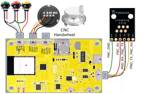
Use the official CYD Dial Pendant guide, specifically Capacitive CYD Wiring with Handwheel and Buttons for the intended capacitive board. Here is the direct diagram linked by that guide. The official guide's GitHub source is a useful fallback if the wiki is unavailable. Refer to V1 Engineering's Jackpot3 documentation for that controller.
Follow the official diagram for electrical connections and cable checks. With power disconnected, keep unused conductors insulated and route the wiring clear of screw ends, button terminals and PCB edges before closing the case.

Harness routing before the CYD is seated, beside the seated CYD
5. Close and finish

The seated CYD before and after the cover is fitted
Join the cover, PCB, middle base, and shell with four M3 × 18 screws. Start all screws by hand, tighten evenly, and check for bottoming in inserts or overtightening in plastic. Confirm touch-screen clearance, USB/microSD access, and free handwheel movement.
Fit the handwheel knob with its M3 × 12 screw, checking that it rotates freely.

The assembled case before and after fitting the handwheel knob
Left: before the knob. Right: the knob fitted to the handwheel.
Recommended firmware
Use FluidDial-CYD by dJOS1475 for this three-button build. I installed v2.2.5. Use the project's web installer and follow its current installation and setup instructions.
For board-specific wiring and controller setup, follow the official CYD Dial Pendant guide and the firmware documentation linked above.
Troubleshooting
A seam will not close: remove first-layer flare and support remnants, dry-fit the three printed pieces, then check insert seating, wire routing and screw length before tightening further.
The jack will not latch: check the board's locating pegs, clamp orientation and cable-latch clearance. Do not force a different jack revision into the slot.
Buttons bind: confirm 7 mm bushings and the actual nut/body dimensions; check that tightening the metal nuts has not caused binding.
The handwheel catches: check all three mounting fasteners and the knob screw for excess projection, and keep wires outside the rotating area.
Official links
Reference | Use it for |
|---|---|
Board-specific wiring and controller setup | |
The diagram linked from the official guide | |
A fallback copy of the guide | |
Recommended pendant firmware for this three-button build | |
Documentation for that CNC controller |
Credits and Makes
Original low-profile case: V1 Engineering, Printables model 1383830. This is a remix. Pendant firmware: FluidDial-CYD by dJOS1475, derived from FluidDial.
If you print one, please post a Make with your board marking, printer, material, settings, and fit results. A photo of the jack and handwheel hardware is especially useful when a supplier changes revisions.
Plain models are supplied under CC BY-NC-SA 4.0; see attribution and license in the ZIP. The source notes explain what can be rebuilt and which parts are supplied as STL baselines.