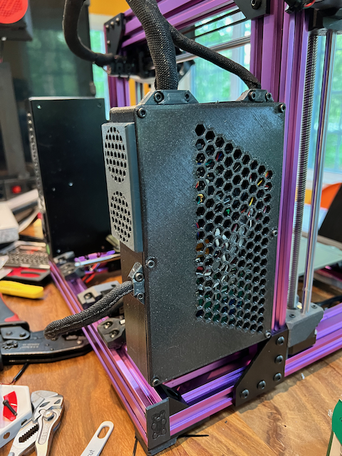
Einsy Pinsy Control Box for Prusa Bear 2.1
Obliczymy ostateczną cenę na podstawie wybranego pliku. Sprawdzisz ją i zaakceptujesz przed płatnością.
Wstępna wycena dla PETG
2,57 € – 3,14 € netto (bez VAT)
Dla pliku: Einsy_Pinsy_Small_Parts_0.2mm_PETG_MK3S_3h19m.gcode
To wstępna wycena jednego pliku. Dokładną cenę poznasz przed zamówieniem.
Plik i założenia wyceny
Plik użyty do wyceny
Średnia wycena orientacyjna: 2,85 € netto (środek widełek).
- Masa podana przez autora
- 28 g
- Czas druku podany przez autora
- 3,31 godz.
- Materiał u źródła
- PET
- Materiał wyceny
- PETG
- Drukarka wyceny
- Bambu Lab P1S - 0.4 nozzle
- Proces wyceny
- 0.20mm Standard
Orientacyjna wycena wyłącznie wybranego pliku, oparta na masie i czasie druku podanych przez autora. Warianty plików nie są sumowane. Ostateczna cena zostanie obliczona po analizie pliku.
Zapisane na tym urządzeniu.

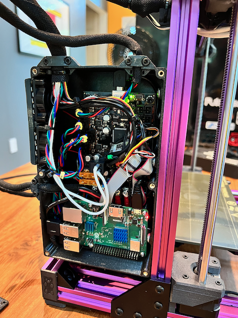
A control box to hold the Einsy and Raspberry Pi that mounts to 2020 Aluminum extrusion on the Prusa Bear 2.1.
- Ocena
- 0 / 5
- Polubienia
- 9
- Pobrania
- 60
- Wydruki
- 0
- Wyświetlenia
- 1301
- Oceny
- 0
Aktualizacja u źródła:
Informacje o modelu
- Źródło
- Printables
- Kategoria
- Prusa Parts & Upgrades
- Licencja
- Creative Commons — Attribution — Share Alike
Introduction
I wanted a control box that met the following criteria, and couldn't find one, so decided to make my own:
- Fits both the Einsy RAMBo and a Raspberry Pi.
- Case fans to prolong the life of the enclosed electronics.
- All parts fit on the MK3 print bed individually.
- No supports required for any printed parts.
- All cabling internal to the box, except what was going to the printer. I had to sacrifice direct access the USB ports on the back of the RPi, but I don't need to access them regularly, and I wanted the cleaner look.
- Use of heat set inserts, which I much prefer to press fit nuts or tapping the threads post processing.
- Mounting for the 2020 Aluminum Extrusion on the Prusa Bear 2.1.
- Breakout 24v power using Wago wire levers for:
- 2x 40x10mm Fans
- Einsy RAMBo
- DC-DC Buck Converter to RPi
Bill of Materials
For the Case:
- 32x M3 5.5x4mm brass heat set inserts
- 24x M3x6mm socket head cap bolts
- 8x M3x12mm socket head cap bolts
- 4x M3x22mm socket head cap bolts
- 5x M5x10mm socket head cap bolts
- 5x M5 T-Nuts (I prefer the spring loaded ones)
- 2x 40x10mm 24v fans
- 2x 5 conductor Wago 221 levered compact wire splicing connectors
- 3M VHB (or similar double sided adhesive tape)
For the Pi:
- 1x DC-DC Buck Converter Adjustable Power Supply Module
- 1x 20cm Angled USB-A Male to Female Extension Cable
- 1x 50cm Angled USB-A Male to Angled USB Type-B Cable
Assembly Instructions
Note that where to cable ports into the Einsy is outside of the scope of this write up. See the official Prusa website for instructions.
Heat Set Inserts
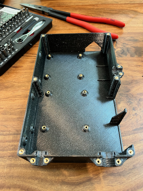
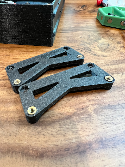
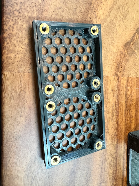
Put in all of the heat set inserts into the following parts:
- Einsy Pinsy Box
- 2x Einsy RAMBo Half Riser
- Fan Grille
Fans
Position the 40x10mm fans against the side of the Einsy Pinsy Box, and fasten them to the Fan Grille with 8x M3x12mm socket head cap bolts. They will sandwich together and hold in place.
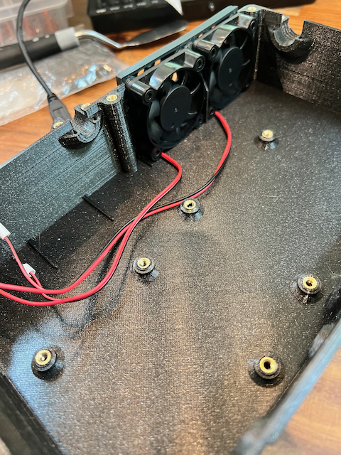
Einsy Riser
Install the Einsy RAMBo riser, and route the fan cables underneath.
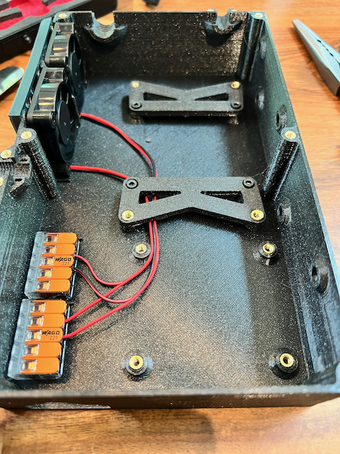
Wire Splicing Connectors
Affix two 5 conductor Wago Connectors to the bottom left of the Einsy Pinsy Box with double sided permanent adhesive tape. Connect the fans. Connect one pair of wires from the power supply.
DC-DC Buck Converter
***NOTE: You will need to tune the output of the buck converter before this step. Make sure you have tuned it, or you may damage your RPi. ***
Connect the buck converter to the wire splicing connectors, ensure you have enough wire length to reach the power port on the RPi comfortably. Find a place underneath the Pi risers for the buck converter to live, and affix it with double sided adhesive tape.
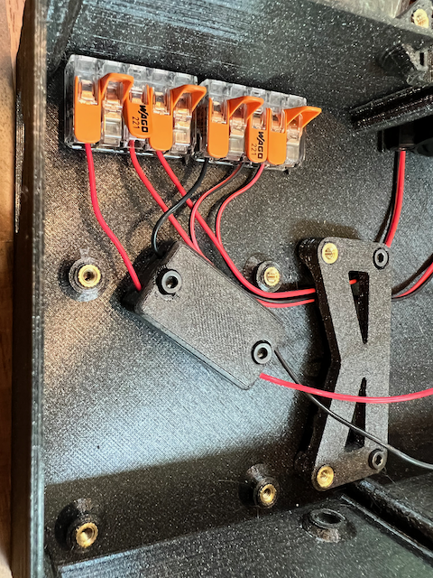
Attach to Frame
Because of the tight space inside the control box, you'll need to attach it to the Bear frame before installing the Einsy RAMBo board. Push the 5x M5x10mm bolts through the side of the box and align with tnuts in the aluminum extrusion of the Bear frame.
Einsy RAMBo Board
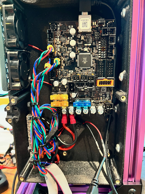
Connect the angled USB Type-B connector to the top of the Einsy board. Secure the Einsy to the control box with 4x M3x6mm screws. Route the USB cable around the corner of the control box and down towards the RPi.
Connect the left most Einsy DC power input terminals to the wire splicing connectors. Connect the remaining DC input terminal directly to the cables coming from the power supply.
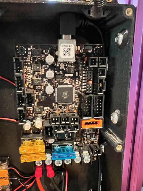
Y/Z-Motor Cables
Route the Y and Z motors through the hole in the bottom of the control box and connect them to the Einsy RAMBo. Neatly wrap and zip tie any excess cabling to keep it out of the way.
Heated Bed Cables
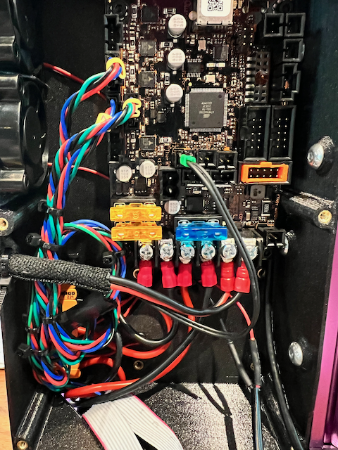
Route the heat bed cables through the side of the box, and connect to the DC output ports of the Einsy. Connect the thermistor cable for the heated bed to the Einsy. Adjust the length of cabling inside of the box and clamp down the strain relief cover over top of the cables at the entry point to the control box.
Extruder Cables
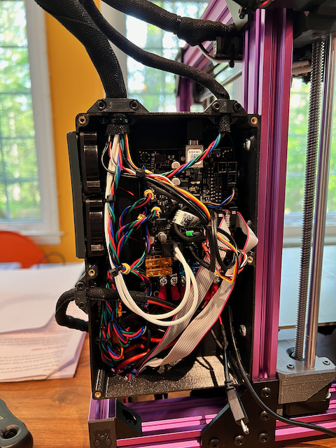
Route the extruder cable bundle through the larger hole in the top of the control box. Connect the extruder motor, and the hot end heater cables to the Einsy board (routing to the left of the board). Connect the remain cables (hot end fan, print fan, filament sensor, and PINDA probe) routing them through the top and right of the board. Adjust the length of cabling inside of the box and clamp down the strain relief cover over top of the cables at the entry point to the control box.
LCD Cables
Route the LCD cables through the bottom of the control box, diagonally under where the Pi riser will go, and plug them into the Einsy.
X-Motor Cable
Route the X-motor cable through the smaller hole in the top of the control box, and connect it to the Einsy.
Raspberry RPi
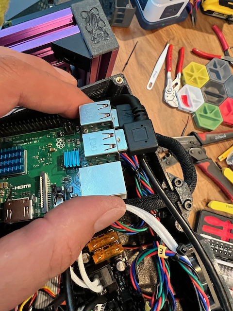
Connect all USB cables, and the power cable, to the Pi. Slot the M3x22mm bolts through the top of the RPi, and through the risers.
Screw the Pi/Riser into the control box, ensuring that no cables are trapped underneath. It's a tight space, so you may need to fiddle a bit.
Final Check
Make sure all of the cabling looks good, and power on the printer. Run it through it's self test and make sure that everything is functioning properly.
Connect to your RPi and make sure it can connect to the printer and webcam (if present).
Screw on the Lid
Making sure not to pinch any wires, secure the lid to the box with 6x M3x6mm bolts.