
Pneumatic-mechanical 4/2-way valve
Obliczymy ostateczną cenę na podstawie wybranego pliku. Sprawdzisz ją i zaakceptujesz przed płatnością.
Zapisane na tym urządzeniu.

4/2-way valve, pneumatically or mechanically actuated. Can also be used as a pneumatic actuator.
- Ocena
- 0 / 5
- Polubienia
- 50
- Pobrania
- 129
- Wydruki
- 0
- Wyświetlenia
- 2868
- Oceny
- 0
Aktualizacja u źródła:
Informacje o modelu
- Źródło
- Printables
- Kategoria
- RC & Robotics
- Licencja
- Creative Commons — Attribution — Noncommercial — Share Alike
Intro
This valve is a 4/2-way pneumatic valve which can be pneumatically or mechanically operated. The valve can also be used as an actuator to move other things.
The valve has six pneumatic ports. The topmost two are for actuating the internal cylinder. The other four are the valve ports which are interconnected either horizontally or vertically, depending on the valve state. The valve has markings on top of the disc to visualize whether the current port interconnection is horizontal or vertical.
Video
This video demonstrates the pneumatic Turing machine which makes extensive use of the pneumatic valve.
The valve itself is explained in the video from 0:32.
Extra components needed:
10x M2 x 16 mm
10x M2 nut
1x M3 x 16 mm
1x M3 washer
2x M3 nut (or 1x M3 lock nut)
6x M5 x 4 mm pneumatic fitting (link)
M5 bottoming tap, or any M5 bolt to make a makeshift tap
Mechanical tools
Two seals from 1 mm silicone rubber sheet cut to approx. 14.1 x 10.1 size with slanted edges (using seal cutter tool)
Sealant such as blue silicone
Petroleum jelly grease ("vaseline", optional)
Pneumatic equipment with 4 mm tubing
Printing instructions
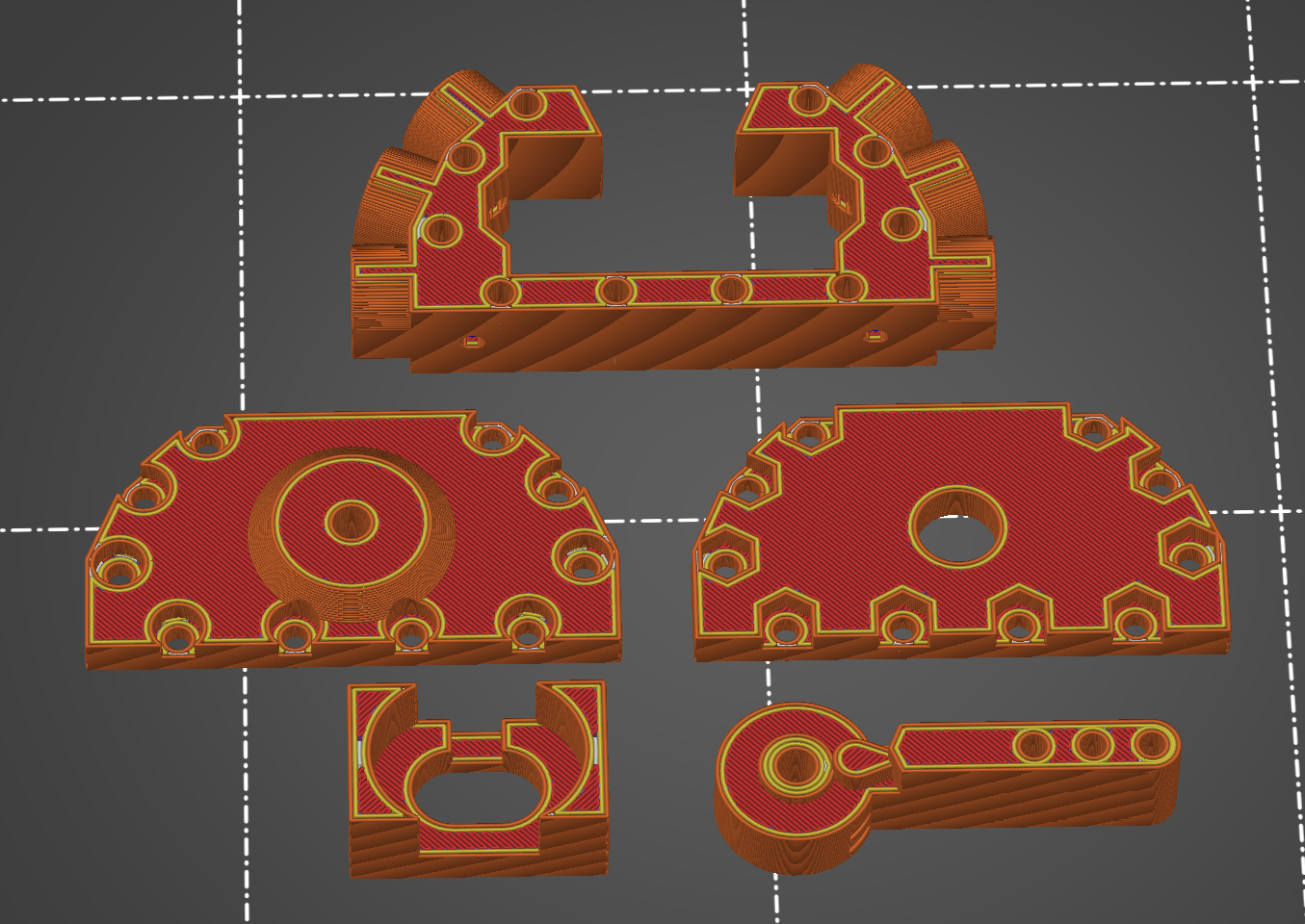
Use a smooth printing surface. 100% infill. PLA is fine for all parts. Make sure no warping occurs.

Post-processing and assembly instructions
Housing: make top surface smooth by sanding. (This can also be done by activating the ironing setting in 3D printing of the housing.)

Tap the six pneumatic access holes with a suitable M5 tap. (If you do not have a suitable tap then you can make one yourself using a M5 bolt and a small metal saw or dremel.) Screw in the six M5-to-4mm pneumatic sockets.

Enlarge the valve hole (but not the rear cover hole!) to 3 mm using a drill, apply some lubricant between valve and rear cover and screw in the M3 x 16 mm screw with washer as shown in the photo. Adjust tightness such that there is some amount of friction in the valve but not too much, it should still be easily movable without too much force. Lock the screw using two M3 nuts (or one lock nut).
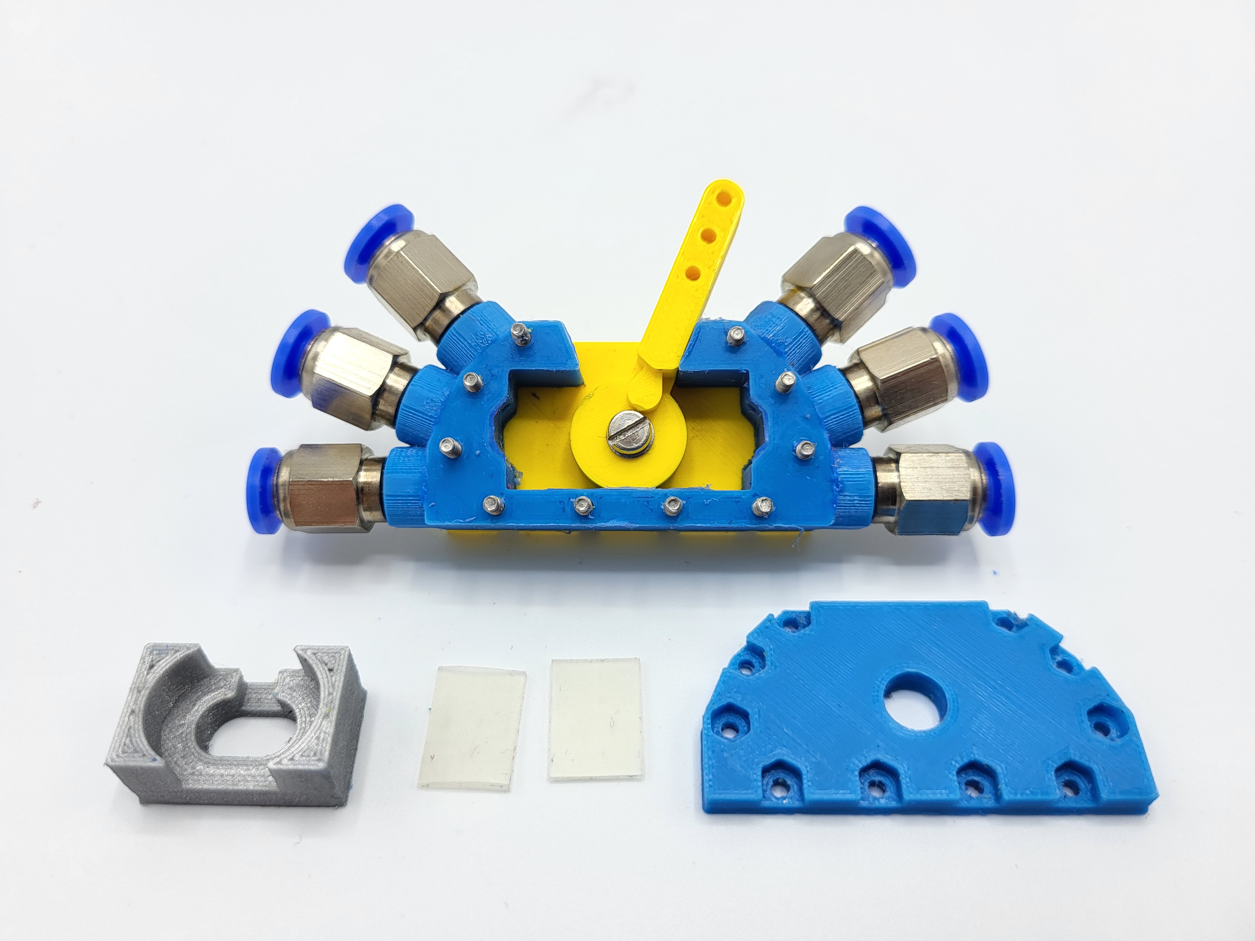
Apply blue silicone on the housing, watch out that air holes do not get clogged. Insert the ten M2 x 16 mm screws.
Prepare the seals (dimensions approx. 14.1 x 10.1 mm) from 1 mm silicone rubber sheet using the seal cutting block (nominally 0.1 or 0.2 bigger than final seal dimensions); you can generate one using the seal cutting tool (also see video) to find the optimal dimensions such that friction and leakage are both relatively low.

Grind the sides of the piston until it can move smoothly in the housing. Apply some vaseline to the piston and seals and insert these in the housing as pictured. Seals have slanted edges so these have a larger face and a smaller face. The larger face must be oriented towards the air chamber, the smaller face adjacent to the piston. This ensures that the air remains trapped in the chamber.

Assemble the top cover, screw tight and the pneumatic valve is ready!
Testing and adjustment
Use the top two pneumatic ports to operate the internal cylinder. Ideally it should require less than 0.5 bar to operate it. Also test the amount of leakage. Adjust the tightness of the valve if necessary by tightening/loosening the M3 screw using a screwdriver and wrench, this can be done in the assembled state.
Finally, the baseplate is useful for joining four valves together.