
1 / 25
Music reactive matrix LED cube
Zamów wydruk tego modelu
Obliczymy ostateczną cenę na podstawie wybranego pliku. Sprawdzisz ją i zaakceptujesz przed płatnością.
Zapisane na tym urządzeniu.
Music reactive matrix LED cube
- Ocena
- 5 / 5
- Polubienia
- 51
- Pobrania
- 108
- Wydruki
- 1
- Wyświetlenia
- 2102
- Oceny
- 1
Aktualizacja u źródła:
Informacje o modelu
- Źródło
- Printables
- Kategoria
- Electronics
- Licencja
- Creative Commons — Attribution — Noncommercial
SzczegółyPliki (6)Wydruki i komentarze (Wydruki: 1) (Komentarze: 1)Remiksy (0)Kolekcje (72)Powiązane
Music reactive matrix LED cube. Very easy print and electronics installation.
Functions:
- 9 music reactive vu-meters and 3 non-music reactive animations
- Currently 1 vu-meter with user selectable color
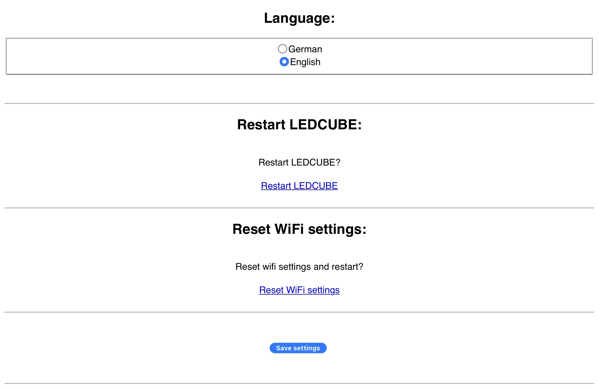
- Web interface to change settings, update the code and reset the WiFi settings to default
- The web interface is available in german and english language
- In the settings you can choose your favourite vu-meters and animations to reduce button presses to switch between your favourites
- With a short press on the button you can cycle through the vu-meters and animations. Green LEDs in the corners show your input as reply
- With a longer button press you can step back to the 1st selcted vu-meter/animation. Red LEDs in the corners show your input as reply
- WiFi manager usage with a captive portal to setup your WiFi connection without the need of changing the code
- Simply upload the code to the ESP with Arduino IDE. No code changes really needed to use the project. Settings can be done in the web interface
- Code updates can be done without Arduino IDE with the use of the provides .BIN file
Web interface:

LEDs and status LED colours during startup:
- White squares will be shown raising from the bottom to the top to check the wiring
- In the matrix corners blue LEDs will show that the device is not connected to WiFi yet. If you start the cube for the first time, connect to the temporary WiFi access point "RGBLEDCUBE" created by the ESP and follow the WiFi setup. If your smartphone, tablet or computer does not navigate to the URL “http://192.168.4.1” automatically, please open this URL manually after you connected to the WiFi access point “RGBLEDCUBE”
- After the WiFi settings were set correctly the blue LEDs will turn green on a successfull connetion to your local WiFi or will turn red if the connetion to your local WiFi was not successful. In this case the temporary WiFi access point "RGBLEDCUBE" will be created again by the ESP to change the local WiFi values from step 2
- After a restart the corner LEDs will always shortly turn blue and then green when the device is connected to your WiFi. The settings page then can be used. Check the URL to connect to in your Arduino IDE serial monitor output after startup
- A short rainbow animation will be shown to check the function again
- Note: The animations used in step 1 and 5 can be switched off in the settings
Video:
Music credit: Used some free music from Apple iMovie
Hardware used:
- 1x Node MCU V3 ESP8266
- 1x Microphone MAX4466 (Please use this one. Cheaper ones do not work well!) Ø9.6mm
- 1x Push button Ø12mm
- 1x Barrel jack for power input Ø12mm
- 5x LED matrix 8x8 (Please use this one. Others might not fit to the case!)
- 1x 5V / 4A power supply with barrel jack connector
- Some 0,25mm² wires in different colours
- Some 0,50mm² wires for the LED matrix power wires
- 18x Soldering cable shoes M3
- 30x M3x8 screws
- 21x M3 nuts (30 if you want to fix the panels even more in place, but not really needed)
Wiring instructions:
| ESP: | LED matrix (1,3,4,5): | Power jack: | Microphone: | Push button: | Wire color: |
| VCC | 5Volt | +5V | red | ||
| GND | GND | GND | black | ||
| ID6 | DIN | green | |||
| 3.3V | VCC | red | |||
| GND | GND | black | |||
| A0 | OUT | orange | |||
| D5 | Pin 1 | blue | |||
| GND | Pin 2 | black |
- Wiring order the 5 matrix and cube sides:
- Matrix 1: As shown above from the ESP —> Front side
- Matrix 2: From matrix 1 as shown in the wiring diagram as 2nd panel —> Top side
- Matrix 3: As shown above from the ESP —> Right side
- Matrix 4: As shown above from the ESP —> Back side
- Matrix 5: As shown above from the ESP —> Left side
- Please follow this cube sides order to make the code work correctly.
- Please take a look at the photos and take care of the screw orientation to avoid electric shorts between the top matrix and the front as well as the back matrix. The screws of the top matrix are switched 180° to avoid electric shorts between the TOP, FRONT and BACK matrix!

Code:
- The code can be found on my GitHub repository.
⚠ Important notes: ⚠
- The provided code limits the amount of simultaneously used LEDs, used colours, their intensity and therefor the power usage to fit to a 20W power supply with 5V/4A! Take care of this too when changing the code!
- Raising the intensity, used colours or simultaneously used LEDs can easily drain to much power and can end in dangerous usage of the power supply and the connections between the panels and other devices/wires used in this project!
- Example:
- Setting all LEDs on 1 matrix panel only to 100% intensity and white color will drain already 3.3A already - on 1 single matrix only!
- For the 5 matrix panels used in this project the 100% white setting would try to use 16.5A and would cause to drain more than 4 times the possible amperage of the power supply. This will not end good… Take care… Seriously !!!
- All provided vu meters were set to values to take care to not drain more than the 20W out of the power supply.
- Use a good and secure ≥5V/4A power supply to avoid serious damage!
- The real question about this all is, if you will actually need higher values of f.e. the intensity. The in the video and pictures shown animations were set to a value of 15 from up to 255 which already is really bright as shown…
- The software limits the slider to the value 128 of 255 to avoid overload of the power supply.
Printing instructions:
- 0.3 draft profile used
- No supports needed
- No brim needed
Happy printing :)