
Brace for Photography Stand
Obliczymy ostateczną cenę na podstawie wybranego pliku. Sprawdzisz ją i zaakceptujesz przed płatnością.
Zapisane na tym urządzeniu.
These are clamps to use a PVC pipe as a brace to prevent a photography stand from sagging down from 90 degrees.
- Ocena
- 0 / 5
- Polubienia
- 4
- Pobrania
- 26
- Wydruki
- 0
- Wyświetlenia
- 561
- Oceny
- 0
Aktualizacja u źródła:
Informacje o modelu
- Źródło
- Printables
- Kategoria
- Tools
- Licencja
- Creative Commons — Attribution — Noncommercial
About This Project:
These are the braces to create an extra support for a camera mount. The brace parts labeled “B” go together for the bottom brace, and the parts labeled “T” go together for the top brace. The top and bottom braces are designed to go around slightly differing size poles.
Dimensions:
- Both braces have a hole to hold the PVC: 2.21 cm diameter
Bottom Brace (“B”):
- 8 cm tall x 6.6 cm wide
- Semi-circle part: 2.65 cm diameter designed to go around 8 cm pole
Top Brace (“T”):
- 8 cm tall x 6.28 cm wide
- “T” brace semi-circle part: 2.28 cm diameter designed to go around 7 cm pole
Assembly Instructions:
This assembly requires additional material:
- PVC pipe with a 6.77 cm circumference (=2.155 cm outer diameter), cut to be about 21 cm long.
- #8-32x1/2” screws (x8)
- #8-32 nuts (x8)
- A screwdriver
- Optional: strong tape
For each brace, there are two sections that come together around the stand that you are securing the brace to.
The brace parts marked “B” are the bottom brace parts and attach to the vertical pole.
The brace parts marked “T” are the top brace parts and attach to the horizontal pole.
 https://media.printables.com/media/prints/379301/rich_content/fba59e9d-95cc-4ebd-873d-b945aa0a3b09/image.jpeg#%7B%22uuid%22%3A%224c634282-2f13-4f32-9c8a-15a634d479bb%22%2C%22w%22%3A411%2C%22h%22%3A547%7D" alt="A picture containing indoor, weapon
Description automatically generated"><img class="image_resized" style="width:27.78%;" src="https://media.printables.com/media/prints/379301/rich_content/d7787542-2081-4ad5-ae5b-68e12956c9a4/image.jpeg#%7B%22uuid%22%3A%22e4eab2d9-6010-4897-8300-16c75e8bc1d6%22%2C%22w%22%3A407%2C%22h%22%3A543%7D" alt="A picture containing indoor, tripod

Description automatically generated"><img class="image_resized" style="width:27.59%;" src="https://media.printables.com/media/prints/379301/rich_content/256b35d0-319a-4d1a-bc00-130836fbe625/image.jpeg#%7B%22uuid%22%3A%2226679672-e705-4502-a044-783737209409%22%2C%22w%22%3A416%2C%22h%22%3A554%7D" alt="A picture containing indoor
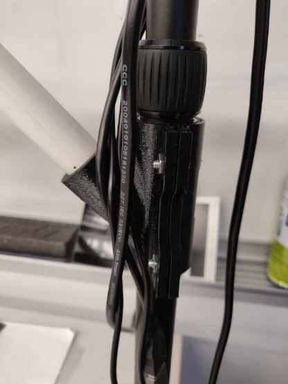
Description automatically generated">
This is what it should look like when assembled:
<img class="image_resized" style="width:42.02%;" src="https://media.printables.com/media/prints/379301/rich_content/4ec73d15-0fbc-4f7d-8d41-1eb1c952029c/image.jpeg#%7B%22uuid%22%3A%2215599fe1-6dc7-4bb3-8629-19a76db4f846%22%2C%22w%22%3A483%2C%22h%22%3A644%7D" alt="A picture containing indoor, weapon
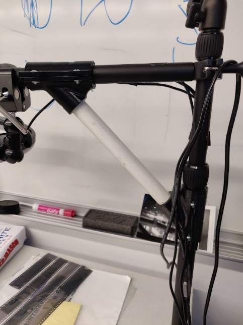
Description automatically generated">
Optional: Use tape for extra security around the bottom brace and the stand to ensure that the brace does not move.
The Objective:
The purpose of this project was to create a brace that can support and strengthen a photography/camera stand as seen below:
<img class="image_resized" style="width:45.55%;" src="https://media.printables.com/media/prints/379301/rich_content/57addcf1-ff5d-4b63-94c1-ddd6d5985ac9/image.jpeg#%7B%22uuid%22%3A%224b4f4a17-b21a-4605-a5ad-a0a923fad68b%22%2C%22w%22%3A710%2C%22h%22%3A532%7D" alt="A coffee maker on a table

Description automatically generated with low confidence">
The Design Process:
The brace needed to be angled across the two poles to keep the stand angle between them perpendicular to each other. This was the design idea I was given:
<img class="image_resized" style="width:22.89%;" src="https://media.printables.com/media/prints/379301/rich_content/b5be164a-12c4-43a4-b02e-30d153942448/image.jpeg#%7B%22uuid%22%3A%22c0e15698-f820-4bc4-8bcb-a39a0d15ca1d%22%2C%22w%22%3A203%2C%22h%22%3A387%7D" alt="A picture containing text, whiteboard

Description automatically generated"><img class="image_resized" style="width:49.7%;" src="https://media.printables.com/media/prints/379301/rich_content/95441952-af26-4a9c-a1ea-66f4609cc040/image.jpeg#%7B%22uuid%22%3A%22296de334-64c5-4c3a-b107-25cd5961b3e7%22%2C%22w%22%3A479%2C%22h%22%3A416%7D" alt="A picture containing text, whiteboard
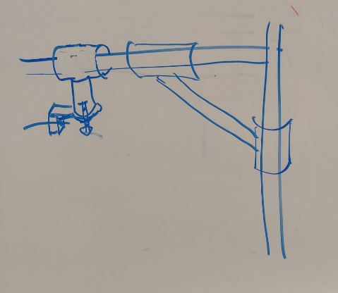
Description automatically generated">
I started by sketching out ideas and possible design ideas. I also took measurements of the stand, and used those measurements to calculate all the dimensions that I possibly needed, as seen in the top half of the photo below:
<img src="https://media.printables.com/media/prints/379301/rich_content/e85dc1e4-25cd-4f5e-8e52-8b7786111e4f/image.png#%7B%22uuid%22%3A%2203eeb0cc-4a61-4b12-9246-d8a2a42ffaff%22%2C%22w%22%3A582%2C%22h%22%3A679%7D" alt="Diagram, engineering drawing
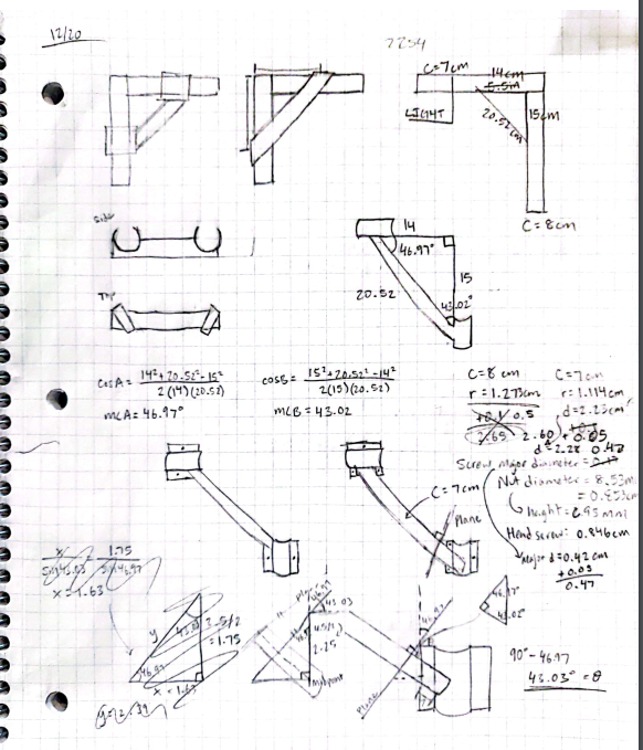
Description automatically generated">
Then, after discussing with the teacher, we decided it would be best to create the brace parts that will attach to the poles of the photography stand and use PVC pipe to connect the two brace parts.
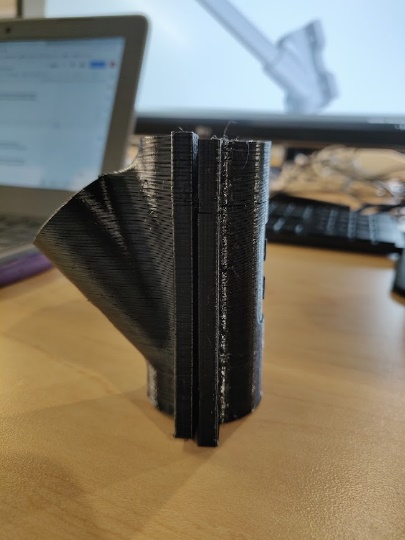
We decided to make the brace in two parts that come together and secure around the photography stand. Instead of having the hole for the PVC pipe on the left side of the body (as seen in the photo below), I originally planned to have two PVC holes (one for each part) on the side facing the camera. So when it is assembled, there would be two PVC pipes.
<img src="https://media.printables.com/media/prints/379301/rich_content/7e693e10-64ed-4646-a8bd-e5976f51b334/image.jpeg#%7B%22uuid%22%3A%22892fbeeb-d481-40e5-9edf-5c3af01e6a17%22%2C%22w%22%3A405%2C%22h%22%3A540%7D" alt="A black rectangular object on a wooden surface
Description automatically generated with low confidence">
I was able to easily create part of the brace that will attach to the pole. Looking at it from above, it looks like a semicircle. I’m going to call this part the “body.” There are also “sides” that come out from the semicircle with holes in them for the screws to go through. This can be seen in the photo below, showing the two parts screwed together. The body includes the two semicircles that come together to create hug the pole, while there are sides coming out of the body for the screws.
<img class="image_resized" style="width:28.12%;" src="https://media.printables.com/media/prints/379301/rich_content/5521dbf8-d20c-41e2-87f2-4fa367fccce0/image.jpeg#%7B%22uuid%22%3A%225d641795-36e3-473c-b9f3-0e8634460161%22%2C%22w%22%3A417%2C%22h%22%3A555%7D" alt="A picture containing floor, ground, black, indoor

Description automatically generated">
The difficult part of this design was angling the hole that will hold the PVC pipe because it needed to be at an exact angle. I thought about many ways to get the angle I needed.
<img src="https://media.printables.com/media/prints/379301/rich_content/fb4c19bb-44a2-46c3-920c-1fb7a06e2871/image.png#%7B%22uuid%22%3A%22dc6376a0-9079-4e56-935b-03111e600897%22%2C%22w%22%3A524%2C%22h%22%3A693%7D" alt="Diagram

Description automatically generated">
I also looked at a similar project for a flag mount, where the hole for the flag was angled. But this did not show me exactly how to angle the hole, since the hole on the flag mount is being angled against a flat side, whereas the brace body part I tried to attach the hole to is rounded.
I was finally able to angle the hole by using multiple reference planes, but I realized that the size of the hole attached to the body was too large. When extruding the hole to attach to the body, the hole is too large. For the design to work properly, the wall thickness on the body would need to be too large.
This is when I decided it would make sense to attach the hole for the PVC to the middle of the body, across the curved part, as seen in the final design.
Then, I created the holes for the screws and added a filet to reinforce the hole for the PVC.
I needed to replicate the design seen in the photo below on the right for the part on the left. Then I needed to repeat both these designs for the top brace. Both the top and bottom brace needed a part with a hole for the PVC pipe, and then there needed to be another piece to help secure the brace to the stand.
<img class="image_resized" style="width:58.32%;" src="https://media.printables.com/media/prints/379301/rich_content/deb18ee9-ae36-47c6-87a9-8773f0e08462/image.jpeg#%7B%22uuid%22%3A%22ad065f66-85cc-4732-be91-5e469df245a2%22%2C%22w%22%3A809%2C%22h%22%3A607%7D" alt="A picture containing text

Description automatically generated">
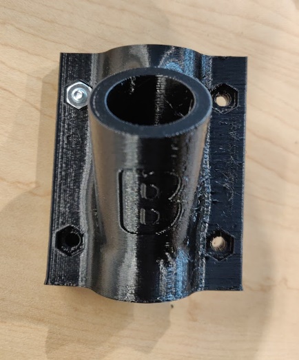
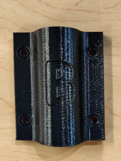
Then, I added indents around the screw holes for the nuts (left photo) and top of the screws (right photo):
 <img class="image_resized" style="width:32.28%;" src="https://media.printables.com/media/prints/379301/rich_content/39f87efd-af63-4a5c-8fea-8cf17653a3c2/image.jpeg#%7B%22uuid%22%3A%22a48cea12-7f70-4774-8b63-00e4957d77ed%22%2C%22w%22%3A417%2C%22h%22%3A556%7D" alt="A picture containing floor, sitting, indoor, case
Description automatically generated">
Because the photography pole for the bottom brace is 8 cm and the pole for the top brace is 7 cm, I added letters to differentiate which brace goes on each pole.
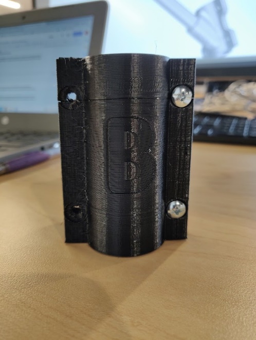
We printed the first version but the screw holes were too small. I used an electric drill with 2 different sized bits to make the holes larger. This partially worked, but this caused some of the brace to crack (above the letter B).
<img class="image_resized" style="width:31.43%;" src="https://media.printables.com/media/prints/379301/rich_content/29a627cc-77c4-40bc-b573-6eb7f4549375/image.jpeg#%7B%22uuid%22%3A%2210aca1e0-e929-43b0-b091-8e1b6b1a7876%22%2C%22w%22%3A498%2C%22h%22%3A662%7D" alt="A picture containing indoor, case
Description automatically generated"> <img class="image_resized" style="width:31.64%;" src="https://media.printables.com/media/prints/379301/rich_content/fc57bc5a-f781-4870-ab3d-778774bc1357/image.jpeg#%7B%22uuid%22%3A%229b09dfa2-b23c-478c-bfbc-c3a3ddec53b1%22%2C%22w%22%3A650%2C%22h%22%3A866%7D" alt="A picture containing text, lighter

Description automatically generated">
I modified the holes to be the right size, and I made the sides that hold the screws to be 50% longer to prevent cracking in the future. I also added filets to the sides where they attach to the body for extra reinforcement.
I used the broken print to test the PVC pipe hole size, and it was a little too large. I realized that I added 0.1 to the diameter as tolerance, which was too much. I decreased the tolerance to 0.05.
After these changes, I printed another.
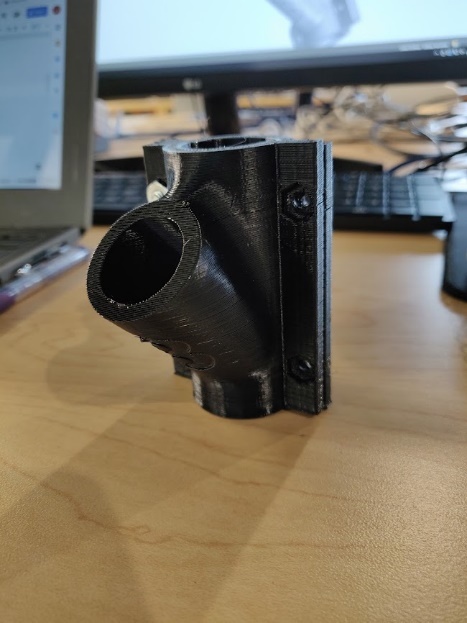
The screws fit into the brace parts and fit on the photography stand perfectly:
<img class="image_resized" style="width:28.57%;" src="https://media.printables.com/media/prints/379301/rich_content/753abd4e-8515-42a4-b769-f4deba13e4a4/image.jpeg#%7B%22uuid%22%3A%22d8a1ae84-d078-4f01-8144-31200b95e335%22%2C%22w%22%3A432%2C%22h%22%3A576%7D" alt="A picture containing indoor, black

Description automatically generated">
But the PVC hole was still a little large. I checked the size of the PVC again and realized that it is smaller than my original measurement. I thought the circumference was 7 cm, but it is actually 6.77 cm. I changed the diameter of the hole from 2.28 cm to 2.205 cm.
I also used the printed model to check to see if the braces fit on the stand, since I was having issues with the tolerance with the PVC. But the braces fit well and there were no changes needed.
The last thing I changed was cutting out part of the side between the two screws and adding filets. This saved some material and made it look better.
The different models can be seen below:
<img class="image_resized" style="width:65.43%;" src="https://media.printables.com/media/prints/379301/rich_content/75f7ce0a-d18e-4e63-8c42-33341ecb399c/image.jpeg#%7B%22uuid%22%3A%22f4ac4041-c31a-42ab-ad54-2de827ba88c4%22%2C%22w%22%3A1155%2C%22h%22%3A866%7D" alt="Text

Description automatically generated">
The final model:
<img class="image_resized" style="width:27.41%;" src="https://media.printables.com/media/prints/379301/rich_content/d3051741-623f-4eb5-87b4-812f8ce91629/image.jpeg#%7B%22uuid%22%3A%222958284e-4581-46ce-90cd-e328b7a5b5e7%22%2C%22w%22%3A478%2C%22h%22%3A637%7D" alt="A picture containing indoor, wooden, floor, wood

Description automatically generated"> <img class="image_resized" style="width:30.91%;" src="https://media.printables.com/media/prints/379301/rich_content/d3480ec2-1356-4e66-8d95-5db3eea4af5b/image.jpeg#%7B%22uuid%22%3A%22bb99a8c4-6b9b-456e-9223-327893b293dc%22%2C%22w%22%3A733%2C%22h%22%3A866%7D" alt="A picture containing floor, indoor, wooden, weapon

Description automatically generated">
<img class="image_resized" style="width:29.21%;" src="https://media.printables.com/media/prints/379301/rich_content/ff3fd19c-0702-4976-94d7-0c4ba8648474/image.jpeg#%7B%22uuid%22%3A%22b770fb03-0f8e-4036-9521-3bab43d67756%22%2C%22w%22%3A411%2C%22h%22%3A547%7D" alt="A picture containing indoor, weapon

Description automatically generated"> <img class="image_resized" style="width:28.61%;" src="https://media.printables.com/media/prints/379301/rich_content/73ab3e3e-e9f5-4f1d-a009-782713b059ac/image.jpeg#%7B%22uuid%22%3A%22bbb96a49-3e90-4878-8830-77f96b8c7c78%22%2C%22w%22%3A407%2C%22h%22%3A543%7D" alt="A picture containing indoor, tripod

Description automatically generated"> <img class="image_resized" style="width:28.34%;" src="https://media.printables.com/media/prints/379301/rich_content/39c65f6f-d222-4f96-abae-daeb4388f3ca/image.jpeg#%7B%22uuid%22%3A%229e53822d-7d17-4cb7-8f68-30dd2069918c%22%2C%22w%22%3A416%2C%22h%22%3A554%7D" alt="A picture containing indoor

Description automatically generated">
The bottom brace did slide up and down the pole a little bit, so the brace needed to be taped to the pole for the extra grip.