
ToolkitRC M6D 6S2P 18650 field charger
Obliczymy ostateczną cenę na podstawie wybranego pliku. Sprawdzisz ją i zaakceptujesz przed płatnością.
Zapisane na tym urządzeniu.

A case to hold a ToolkitRC M6D charger and 6S2P 18650 powerbank. With optional Molle mount for Torvol Urban Carrier
- Ocena
- 0 / 5
- Polubienia
- 20
- Pobrania
- 60
- Wydruki
- 0
- Wyświetlenia
- 2910
- Oceny
- 0
Aktualizacja u źródła:
Informacje o modelu
- Źródło
- Printables
- Kategoria
- RC & Robotics
- Licencja
- Creative Commons — Attribution
Features
Removable power bank tray
The power bank tray slides in and out easily, and is secured with clips. Accessing your 18650 batteries is very fast. Furthermore, the 18650 holder is an off-the-shelf part requiring minimal soldering (One bridge, and soldering on of XT60 and balance leads)
Power switch
You can turn on or off the charger using a power switch
Compartment for LiPos
LiPos which are being charged can sit inside a locking compartment (Fits up to about a 1000mAh pack), allowing you to continue storage charging on your way home.
Proper LiPo connectors
Adapters are used so that LiPos connect to proper JST-XH balance connectors.
No more trying to remember which end of the balance lead connector is negative, you have proper keyed JST-XH plugs.
Also, you can optionally have an XT60 / XT30 Y cable on each of the discharge ports, so you do not need to carry around adapters
Molle mount (Optional)
Features a spring loaded catch mechanism which attaches to Molle straps.
Any triple hole Molle strap mount sould work, although this is designed to mount on the right side of a Torvol Urban Carrier. Holds up to 2 Charging Stations.
Fully Open Source
Fusion360 CAD files are provided for you to mod and remix
Instructions
Unless otherwise stated, all parts may be printed in pretty much any rigid material (PLA is fine). Flexibles (eg TPU) will be needed for some parts.
“Sacrificial Layers” are used for various screw holes to make the recesses for screw heads able to be printed cleanly. Before assembly, a number of these holes will need to be drilled out (Or push something through - they are only 0.4mm thick)
-------------------------------------------------------------------------------
Power bank section
=== Printing ===
- Print
Bottom. The battery tray sits in this part.
Drill out the Sacrificial Layers in the marked holes
- Print
Battery tray
This holds the PCB containing the batteries - If you have a power switch, print
Header, else printHeader no power switch
The power bank connectors (XT60, 6S balance lead), and optionally the power switch mount to this. - Print the
Balance lead stopper 6S(At least one, optionally two) in a flexible material.
This acts as strain releif, to make sure you do not yank on the balance lead plug and rip it off.
At this point, you may skip forward to assembly while the other parts print. - Print 2x
Tray clip. Recommended to use solid infill
These allow easy removal of the battery tray - Print the
XT60 retainerandBalance lead retainer
These clamp the XT60 and balance lead connections, and allow you to remove the header without having to de-solder wires from the PCB
=== Assembling ===
WHEN WORKING ON THE PCB, DO NOT HAVE IT POPULATED WITH BATTERIES
- Prep the PCB
Bridge the two pads in the bottom left of this picture. If you do not do this, then the XT60 positive pad will not be connected.
Also familiarize yourself with where the XT60 and balance lead will connect
- Solder your balance lead.
Before soldering the balance lead, thread the wires through theBalance lead stopper 6S
These are the blue parts in the picture
At least one of these is needed (The one on the right) - it's job is strain releif and it is important for safety.
The one on the left is intended to allow you to slot the balance lead inside the case, but to be honest it does not really work, so feel free to not use it.
When viewing from the bottom, the most positive wire is the one at the bottom of the picture below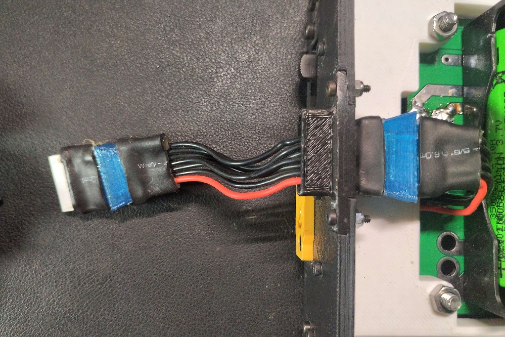
- Attach the
PCBto theBattery Trayusing M3 screws and nuts
WARNING! These screws + nuts are LIVE. They are connected to the + and - of the power bank. Whenever you handle the assembled battery tray, BE CAREFUL not to touch them to anything metal. - Attach the
Headerto theBattery Trayusing M2 screws - Solder your
XT60E-Fplug to thePCBvia chunky wires, optionally with aPower Switchin-line.
It is recommended that you solder the positive wire of the XT60 via the switch. If you solder the negative wire in-line, the positive pin of theXT60E-Fwill always be live. - Attach the
XT60E-FandBalance Leadto theHeaderusing theXT60 retainerandBalance lead retainerusing 2x M3 screw and nut for each - Attach 2x
Tray Clipto theHeaderusing 2x M2 screw and nut each
Assembly of the power bank section is now complete. Check that the Battery tray assembly smoothly slides into the Bottom and that the clips engage and do not disengage too easily.
-------------------------------------------------------------------------------
Molle Mount (Optional)
Note: The Molle mount is designed to hold two of the charging stations, so some parts may need to be printed multiple times to hold both.
=== Printing ===
- Print
Top plate
The hex holes should be facing upwards when you print.
Drill out the Sacrificial Layers for the marked holes.
- Print 1x
Spring Clip Femalefor each charging station you wish to mount
This is a 4-part 3MF consisting ofBottom,Top,Arm LandArm Rparts
At this point, you may begin assembly while the other parts print - Print
Base plate
Again, hex nut recesses should be facing up while printing - Print 1x
Spring Clip Malefor each charging station you wish to mount
=== Assembly ===
- Insert M2 nuts into the recesses on
Top Plate - Assemble
Spring Clip Female
Begin by placingArm LandArm R(Shown in blue) in the recesses in theSpring Clip Female (Bottom)part as shown below (Optionally put some grease in the recesses)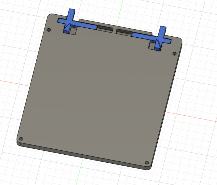
Then place aSpringinto each channel in the space in the middle
Then place theToppart on top
Check that the arms can move freely within the recesses and don't bind (Squeeze them together towards the middle), and that the springs cause them to return to the neutral position properly. - Screw the
Spring Clip Female(One per charging station) assembly to the top plate using 4x M2*12mm screws - these screw into the nuts you installed in step 1 - Insert M2 nuts into the recesses on
Base Plate - Slide the fingers of Base Plate into the Molle straps on your bag
The fingers should point down towards the bottom of the bag
The nuts you installed in the previous step should face inwards, towards the bag. - Screw the
Top Plateto theBase Plateusing 9x M2*6 (ideally) or up to 8mm if you don't have them. Any longer and you may damage your bag. - Drill out the Sacrificial Layers of the marked holes on the
Bottompart of the power bank
- Attach the
Spring Clip Malepart to theBottomusing M2 screws and nuts (Nyloc recommended). Note the orientation of the lugs - they should be near the top of the charger. M2*5 is ideal, but anything up to about M2*7 will do. DO NOT use anything longer as they may damage the 18650s
At this point, the power bank Bottom should attach to your bag and there should be a (very satisfying!) CLICK when it snaps in place. Squeeze the two Arm parts together to release the charger from the bag.
-------------------------------------------------------------------------------
Charger Section
=== Printing ===
- Print
Charger housing
At this point, you can begin to assemble while other parts print. - Print
Lid - Print
Clasp MaleandClasp Female - Print
Lipo coverin a flexible material (I use TPU 98A)
=== Assembly ===
- Prep 2x XT extenders. The charger end is an XT60 female, and the other end needs to have either an XT60 male or XT30 male, or both.
- Prep 2x Balance lead extenders. The charger end needs to be female, and should ideally be a 6S balance lead. The other end should be male, and either should be of the size needed for your LiPos (ie a 5-pin for 4S) or just use a 6S and cut some extra slots in it for the keys.
Here is my setup that supports XT60 or XT30 and 4S or 6S balance leads
Note that if you do not use a 6S balance lead extender, you will not be able to use the charger to balance charge the 6S 18650 power bank!
- Insert the
Lipo Lead Extendersinto the charger, and place the charger inside theCharger Housing
It should look like the picture above.
Be Careful! theCharger Housinghas lips to retain theLipo Lead Extendersand ensure that they cannot come unplugged. It is a bit of a tight fit. - Screw
Clasp Maleto theLipo Coverusing M2*4 screws and nuts. Try to avoid anything longer else you will have exposed screws inside your LiPo bay - Screw the
Lipo Coverassembly to theCharger Housingusing M2 screws and nuts - Screw the
Clasp Femaleto theTop Plateusing M2*4 screws and nuts.
Try to avoid anything longer as it may damage yourLipo Lead Extenders - Insert 6x M2 nuts into the highlighted recesses in the
Charger Housing
Note that the two on the left of the picture will be a bit of a pain to get them in there - suggest putting them on a screw, pushing them into the hole (ensure they are level), remove the screw and then force them down as far as they will go with something (Try and use something with as big of a diameter as possible, it will help to keep them level - A 3mm hex driver is good).
If they become twisted, a really long 2mm allen key (The kind with a right angle at the end) and a hammer can be used to force them back out again.
- Attach the
Bottompart to the Charger Housing part using 6 M2 screws. The two that are next to the vents on the side of the charger (On the right in the pic above) need to be exactly 10mm long - Screw the
Top Plateto theCharger Housingusing M2 screws
-------------------------------------------------------------------------------
Feet
=== Printing ===
- Print 2x
Foot
Each foot is a 2 part 3MF. If you can do multi-material prints, then print the inner core in a rigid material and the main body in a flexible. Otherwise just print in a flexible
=== Assembly ===
- Screw the feet to the bottom of the Charging Station using M2 screws
-------------------------------------------------------------------------------
Final things
- Wire up an XT60 Male to Female with chunky wires. About 80mm cable length is good
- Plug this from the Charger section to the Battery Tray section. If you installed a power switch, you can leave this plugged in all the time and just use the switch to turn the charger on or off.
- To charge the 18650 pack without needing to remove the battery tray, you can run extension leads from the Lipo charging ports on the charger to the XT60 / Balance lead connectors on the power bank, like so (And then power the charger using a AC/DC converter, car cigarette lighter adapter etc)
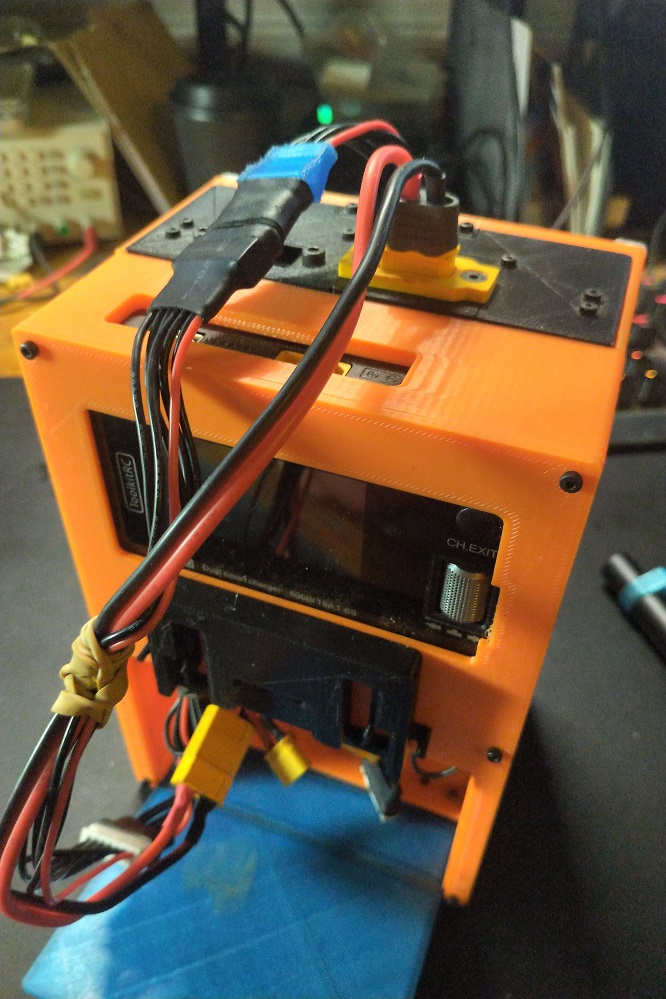
I do not recommend charging 18650s at 1C! I use 0.5C
This also applies if using “Recycle mode” when discharging your LiPos - if discharging two LiPos in Recycle Mode, the Max Current for each should be 0.25C! - I do not recommend turning off the power switch if charging of LiPos is ongoing - it may damage the switch
-------------------------------------------------------------------------------
Parts required
- XT60 plugs. Number depending on preference, but at a minimum 3x XT60 male + female, 2x JST-XH male + female (7 Pin)
- JST-XH male-female extension leads (7 pin).
You will want 2 that are as short as possible (For the LiPo balance lead connections), and 1 that is about 15cm long (To allow you to charge the power bank using the charger itself) - 1x XT60E-F plug
- 1x Power switch (Optional). Either this one or one matching it's dimensions, or edit the project file and adjust for the switch size you wish to use
- 1x 6S2P 18650 holder PCB. You need this one (The “6S2P No BMS” version)
- Assorted M2 screws and nuts. 4mm wide nuts (Ideally 1.4mm high) are absolutely required, Nyloc 1.6mm high nuts can optionally be used for some parts.
A general assortment is required, but some screws need to be specific lengths:
For each Charging Station:
2x M2*10
4x M2*≥10
2x M2*5-6
For the Molle Mount:
4x M2*12mm for each charger
9x M2*6-8mm
These are not all the M2 screws you will need. Otherwise, screws in the 6-10mm range are generally OK - 8x M3 screws (At least 10mm long) with nuts
- (Optional, if using Molle Mount) 2x 10mm long by 3mm diameter springs
- 12x 18650 batteries