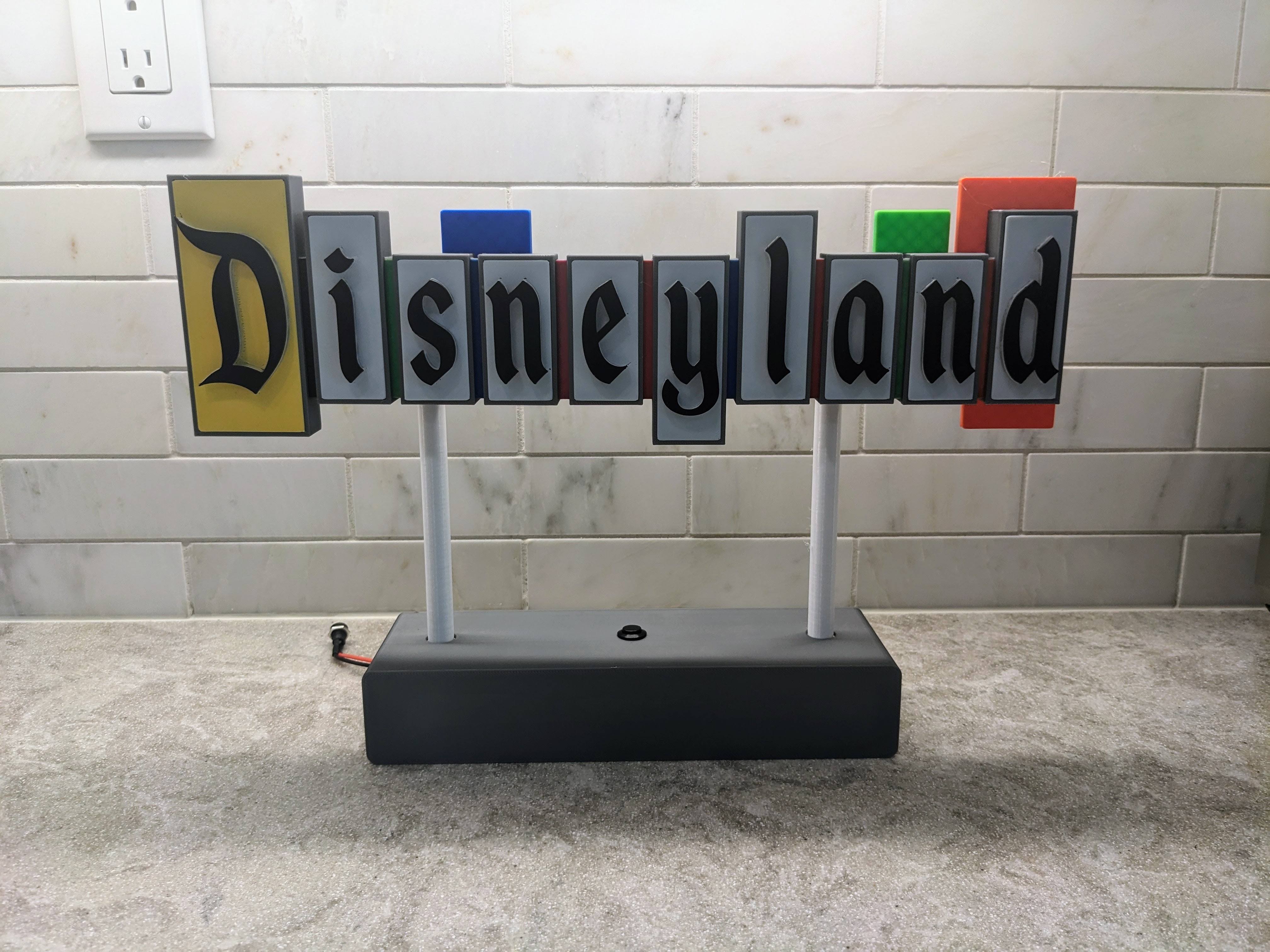
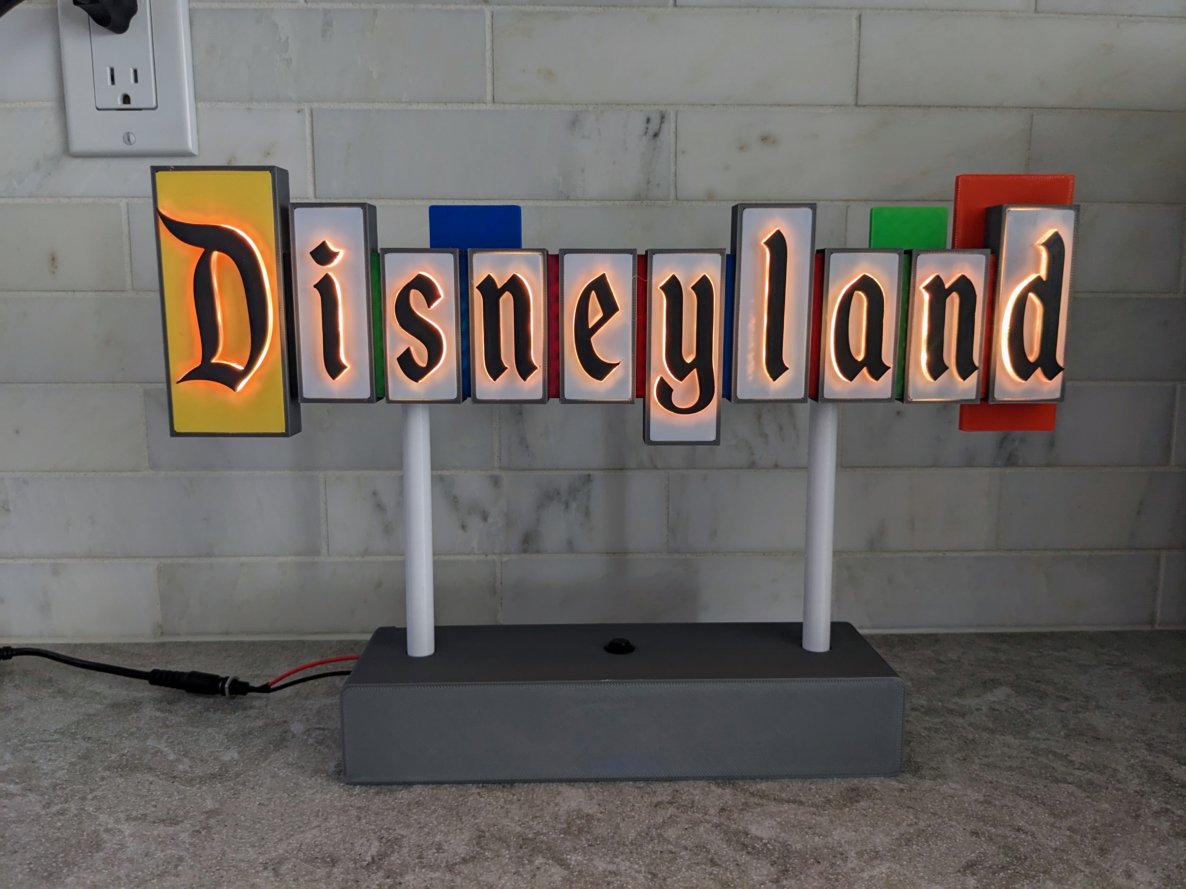
Tabletop Vintage Disneyland Sign (Multi-Material)
Obliczymy ostateczną cenę na podstawie wybranego pliku. Sprawdzisz ją i zaakceptujesz przed płatnością.
Zapisane na tym urządzeniu.

Tabletop sized (14") light up model of the vintage Disneyland Sign
- Ocena
- 0 / 5
- Polubienia
- 134
- Pobrania
- 297
- Wydruki
- 0
- Wyświetlenia
- 1871
- Oceny
- 0
Aktualizacja u źródła:
Informacje o modelu
- Źródło
- Printables
- Kategoria
- Other Art & Designs
- Licencja
- Creative Commons — Attribution — Noncommercial — Share Alike
The original design for this vintage Disneyland sign was a bit big for a table top decoration, so I wanted to shrink it down and take advantage of my Bambu Lab AMS. I made a few improvements to make it easier to assemble (no super glue) and moved the electronics into the stand.
10/10 wouldn't recommend this project as your first foray into LED strips and soldering, because of the smaller size there isn't as much space to hide wires so they need to be shorter and pretty tight. Short wires and tight spaces make it difficult to solder the joints.
I laid the original parts over each other, adjusted scaling so they lined up more uniformly, and exported combined files. There are (technically) 2 versions of this model: Bambu AMS files and stl files. The Bambu 3mf files are pre-painted and ready to go split up on different plates in order to print with a single AMS (this is the version I printed). The other is the updated stl files, ready for a multi-color printer (note that I recreated an approximate versions with the same mounting holes, but haven't printed it myself).
Lighting for this project is powered by WLED running on a Node MCU. So if you aren't familiar with it, highly recommend looking over their documentation here.
3d Printed Parts
- 1 set of combined frames/blocks
- print with supports
- painting in included 3mf files only paints front visible surfaces and minimizes filament changes
- 1 set of combined inserts/lenses
- print in 3 separate colors: black (1-layers), top color (4-layers, yellow for capital D, white for all other letters, transparent lenses
- 1 set of letters (from the original design, scaled to 50%)
- print face down (I printed on smooth plate, but I think it might look nice with the textured PEI plate)
- 1 stand base and back cover (the base is a remix of this model from Thingiverse)
- 1 stand frame
Additional Parts
- LED Strip (I used WS2812B strip, 74/m)
- Node MCU (or some other controller, but the sled is designed for the Node MCU)
- Momentary Button
- Barrel Jack (~12mm diameter body)
- 4x m3x10mm bolt + nuts (attach sign to stand)
- 2x m3x8mm bolt (attach stand to base)
- 1x Wago 221-413
- 1x Wago 221-415
- 22awg wires (20awg is probably better, but 22awg is easier to work with)
- (Optional) 3-pin JST SM connectors/wires, makes it easy to separate the wiring from the sign/frame if you want to disassemble later
Assembly
Assemble the letters and the lenses, by placing the letters over the lense top and applying some hot glue in a few dabs on the inside
Attach the Frames:
The frame segments are attached together using a m3x8mm bolt and a m3 nut. In addition to the holes for the wiring, at the end of each frame segment, there is an additional hole in the middle to insert the bolts through.

LED Segments:
Cut segments for each letter from your LED strip based on the instructions. Double check the spacing of your LEDs and how many can fit inside the letters (don't forget about a little space at the top and bottom for wiring.
The LED strip that I had, which had 70LEDs/m fit about 5LEDs for the D, 4 LEDs for the bigger letters and 3 for the smaller ones. Make sure you check the direction of the strips as you solder them. The direction of the strips snake up and down between each letter. Starting from the top of the “D” at the begging, then going up for the “i” and back and forth.
Once the wiring is completed and verified to be working, a few dabs of hot glue on each segment to center and hold it in place should do the trick. Glue over the contacts and exposed wire ends work as an insulator and adds some strength to the contacts.

Few tips:
- pre-solder the pads for the LED strips before soldering into the frame
- feed the wires through the frame hole prior to soldering to the previous segment, this makes it easier to cut the wire segments to the proper length
- the 3 wires shouldn't be cut to the same length, depending on the direction the 5v or the ground will be the longest and shortest, with the data wire always being in the middle
- e.g. going from the 3rd to the 4th frame segment (bottom), the ground (white) was the shortest and 5v (red) was the longest
- there should be very little slack between the segments because there is no where for the excess wire to go
- test as you go, plug in the segments to a controller to make sure it lights up before moving on to the next segment
Base/Stand Assembly
First attach the stand to the sign using m3x10mm bolts and a nut on the inside.

Once attached, now is a a good time to measure the wiring needed from the end of your light switch wiring to where the NodeMCU will be in the base. Having a JST connector here simplifies attaching/wriing the base to the stand here. You'll need enough wire from the connector, go down one of the stand legs (using the channel to hide the wires) and to at least reach into the center of the base. The image below shows about how much wire you should have in the base.
The stand slides right into the base into the stand holes, there should be a screw hole in each leg that aligns with one in the base. Use one m3x8mm in each leg to attach it to the base.

Next slip the button into the base and wire it up to the Node MCU (data wire from the LED to D4, and ground wire from button to D3) and the ground Wago connector (5-slot wago, 4-slot will be power).
Run the power and ground wires from the sign to the appropriate Wago connectors. Attach the Node MCU to the Wago connectors. Finally you'll need to put the barrel jack connector through the back cover and connect to the Wago connectors.
Last step is to slide the pcb tray into the holder, I found it easier to route the button wires in the middle of the Node MCU and route all the wires and Wago connectors to the side where the wires are coming down.

Now is a good time to do a final test, plug it in, turn on all the lights and make sure you are good to go. All that is left to do is put on the back cover, and put in each letter in the sign.