
Floating Candles - Using Flickering LED and PVC Pipe
Obliczymy ostateczną cenę na podstawie wybranego pliku. Sprawdzisz ją i zaakceptujesz przed płatnością.
Zapisane na tym urządzeniu.

A battery powered floating candle you can hang, uses AAA batteries, latching push button and flickering LED.
- Ocena
- 0 / 5
- Polubienia
- 14
- Pobrania
- 27
- Wydruki
- 0
- Wyświetlenia
- 518
- Oceny
- 0
Aktualizacja u źródła:
Informacje o modelu
- Źródło
- Printables
- Kategoria
- Autumn & Halloween
- Licencja
- Creative Commons — Attribution — Noncommercial
NOTICE: Assembling these took about 30 minutes per candle, and consumed materials worth ~$2 per candle (including batteries). Building these is a large commitment so read through and make sure you're willing to put up with the fussiness. A major improvement to this design would be to redesign this to use a single PCB.
Description:
Using ½" PVC pipe and some small electronic components, create a simple floating candle powered by AAA batteries that you can hang by fishing line. Includes a latching button so you can turn each candle on and off, and with standard AAA batteries (850 - 1200 mAh) should yield 80-120 hours of runtime.
Includes Fusion 360 archive file so you can adjust and tweak the design if your components are sized differently than mine.
Parts List:
- 7mm x 7mm latching push buttons
- Battery spring contact
- Battery solid contact
- 150ohm - ¼ W axial resistors
- 5mm flickering leds (yellow)
- #22 AWG solid wire or smaller. Thicker may not fit.
- Heat shrink
- ½" Schedule 40 PVC pipe (white)
- Hot glue and/or wax for end of pipe (optional)
Instructions:
3D Printing Instructions:
- Print the candle parts as indicated below, a brim is recommended ONLY for the bottom and top parts as the narrow bases can sometimes detach during printing. I recommend white filaments.
- The coupler nut should not need to be printed with a brim as any additional diameter can cause assembly tightness and issues.
- Make sure the coupler nut is printed upside-down for the most surface area against the bed.
- Flame diffusers should be printed out of clear filament with a low amount of infill (5-15%) for best light diffusion (as-tested). No brim was needed in my prints.

PVC Pipe Preparation:
- Cut pipes into approximately 8" lengths. You can cut the ends straight, angled, or any combination.
- Remove any trade markings or laser marks on the exterior of the pipes by sanding them off. You'll want to use a cordless drill or belt sander if doing several. You can try and use a solvent or paint but I haven't tested this.
- Optionally, you can melt wax and dip or drip the wax over the end of the candle for extra effect. If you do this, ensure you don't drip wax inside the pipe as this will make assembly difficult or impossible.
Electronics Assembly:
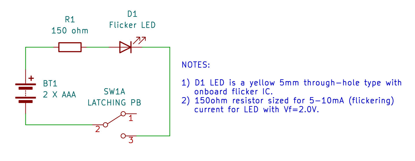
- Decide how many candles you're making and build a prototype, ensure all the dimensions are correct and determine the best wire lengths for each part. To speed up assembly I recommend cutting, soldering and forming each component as a batch.
- You'll need to meter out your push buttons to arrange the pins, and I recommend testing an LED with your batteries/resistor to make sure they're working as expected.
- (Below: Examples of prototype parts, and batched wires/components ready for next steps in assembly).


- Solder the positive lead wires to the battery solid contacts for the top of the batteries:

- Solder the longest wire to the push button. This wire will route to the top of the candle and connect to the negative terminal of the LED:

- Cut and prep the resistors and LED leads (make them shorter), and solder the resistor to the positive leg of the LED:

- Solder the shortest black wire to the battery spring contact (no photo provided).
- Insert the longest black wire (already soldered to the button) through the port hole in the bottom of the base assembly, through the rear window and up the side of the base assembly. Fully seat the button into its hole and secure the wire in the groove with tape:


- Insert the battery spring contact with soldered wire into the base assembly through the top and use the viewing window to help pull the attached wire through the bottom hole. Solder to the push button, making sure not to bridge contacts:

- Insert the solid battery contact with soldered wire into the top assembly. Pull the wire to the side and solder to the resistor/LED. Tuck the resistor/LED into the top assembly and slide a coupler nut over the top assembly:


- Insert 2 x AAA batteries now (or later), and connect the base and top assemblies together by threading the coupler nut together. Stop threading the nut when the grooves are fully aligned, which gives room for the long wire to fit. Route the wire along the grooves, secure with tape, and solder to the negative lead of the LED (don't forget the heat shrink!). Leave the LED pulled to the side so your heat gun doesn't warp the PLA (if you printed in PLA, like I did).

- After you've shrunk the heat shrink, press the LED into place with a small screwdriver (hold the end of the top assembly with your fingers so you don't snap the “end cap” off the top assembly), and press the clear diffuser over the LED - you're done!


- As a final step, look at how much work and time this consumed and question whether it was ever really worth it (it is when you finally turn them all on….):

Final Candle Assembly / Hanging:
- The completed electronics assembly simply slides into the ½" PVC with a friction-fit tightness. If the fit is too loose, apply tape around the coupler nut to increase tightness (I recommend one layer of painters tape or masking tape).
- Hang the candles by wrapping a length of fishing line through the pipe, or using a timber hitch on the electronics assembly alone. I found the easiest was simply wrapping the line through the inside of the pipe around the outside, and putting a hitch around the electronics assembly so it hangs straight. You can also drill a small hole at the top of the PVC for hanging.
Notes on Dimensions/Customization:
- The widest part of the electronics assembly is the coupler nut - this defines the friction fit tightness. I tested and had coupler-nut diameters of 15.0-15.4mm work, and settled on 15.1mm as a “fits in everything” diameter. You can print wider or thinner nuts if necessary.
- Do note that for a given length of PVC, the eccentricity of the pipe can vary slightly, so just because one 8" section fits, doesn't mean they all will. I recommend printing at a smaller coupler nut OD just to be safe (15.1mm, in this case, is a safe bet).
- The position of the coupler nut wire groove depends on how tightly you can screw it down before bottoming out. You want to have the assembly almost fully tight when the groove lines up correctly. I settled on 285 degrees for my prototype. You can change this if your prototype lines up differently.
- You can customize the coupler nut OD and the groove angle using the provided .f3d file:

Final Thoughts / Suggested Improvements:
- This design requires a lot of manual work and some prototyping/design changes if your materials differ slightly from mine. I cannot recommend this for someone who just wants the end-result. I would recommend this for someone willing to tinker or improve on this design, and has decent soldering abilities.
- A future improvement would be to use a single PCB assembly to speed up & simplify the soldering and remove the fussy wire management that is necessary to fit into such a small space.
Credits / Attribution:
- The flame diffuser is based on this model. I slightly adjusted the hole for a tighter fit, and chamfered the bottom.