
QuickConnector for MK3 / MK4 - XT60 (H) Style
Obliczymy ostateczną cenę na podstawie wybranego pliku. Sprawdzisz ją i zaakceptujesz przed płatnością.
Zapisane na tym urządzeniu.
I Decided to create my own Version of the Prusa Enclosure Quick-Connector ...
- Ocena
- 4,6 / 5
- Polubienia
- 146
- Pobrania
- 329
- Wydruki
- 6
- Wyświetlenia
- 3379
- Oceny
- 5
Aktualizacja u źródła:
Informacje o modelu
- Źródło
- Printables
- Kategoria
- Prusa Parts & Upgrades
- Licencja
- Creative Commons — Attribution — Noncommercial
I Decided to create my own Version of the Prusa Enclosure Quick-Connector just because I had some XT60H Connectors on Hand and war curious, how this Project would turn out. Tecnically this Connector can be used for each Printer and every Power Supply. Hope this Project can be useful for someone else out there ;o)
Version History
- 1.0 - First Version of the Quick-Connector an the Documentation
Straight Version / angled Version
There are two Versions available for this QuickConnector. A Straight and an 90° Angled Version. I Decided to go for the straight Version. Consider to print both Housings, in case you change your mind during the build.


I decided to go for an “8 Pin Connection” This should make the Design customizable for each Version and Generation of Printer and / or Power Supply. The Fotos are from my MK4 which has a two Wire Power Panik Connector. If your Printer has just one Wire, leave the other one out.

Hardware
All used Hardware in this Project can be used from the “Spare Part Bags” that came with the Enclosure Kit. I was lucky enough to find also two 3x20mm Pins in my Spare Part Bags.
If you have just one Pin left over, you can use just one Pin, or leave the Pins out. They just provide alignment. Maybe give it a try to print them ;o)
Print instructions
Download the latest PrusaSlicer and use the following settings**:
- Print settings: 0.20mm QUALITY
- Filament: PETG (tested on Prusament)
- 15% Grid infill
** Note that print settings are recommended, but you can experiment with your own.
Needed Parts, Print-Orientation and Supports
All Parts are designed to be printable without Supports, if oriented with the orange colored Face on the Print Bed.
Some Parts are the same for both Versions as described in the following Overview.

- Blue Parts - for angled Version
- Orange - for straight Version
- Purple - for both Versions
For the straight and the angled Housing Print :
- FemaleConnectorCover ( Print 1 )

- FemaleConnectorHolder ( Print 1 )

- MaleConnectorHolder ( Print 1 )

For the straight Housing Print :
- StraightCoverHousing ( Print 1 )
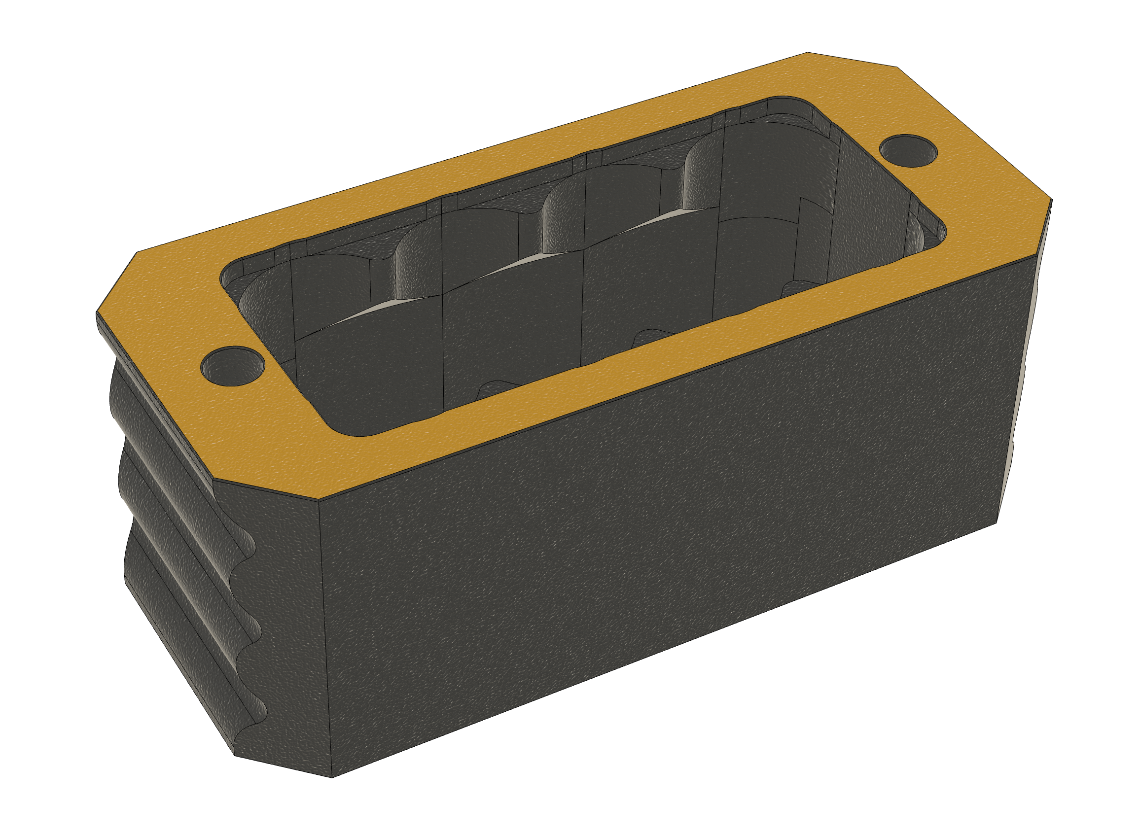
- StraightCoverCap ( Print 2 )

For the angled Housing Print :
- AngledCoverHousing ( Print 1 )

- AngledCoverCap ( Print 1 )

Important - Use the correct XT60(H) Style Connector for this Build !
My Design uses the XT60H Connectors. This Connectors a meant to be used with a small Cover Cap.

It turns out, that the “Lip” on the XT60H Connector fits just perfect in the Cutout of the PSU Mounting Bracket. The Connector needs just a little “Twist”, to go in there.

Assembly Instructions
Prepare PSU and Cables
The “Printer-Side” can be left as is. There is no need to remove the Cable Sleeve completely.

Disconnect all Wires. Be careful with the Power Panic Connector. It has a little Release Hook, that looks it in place! I decided to go for an “8 Pin Connection” This should make the Design customizable for each Version and Generation of Printer and / or Power Supply. The Fotos are from my MK4 which has a two Wire Power Panik Connector. If your Printer has just one Wire, leave the other one out.
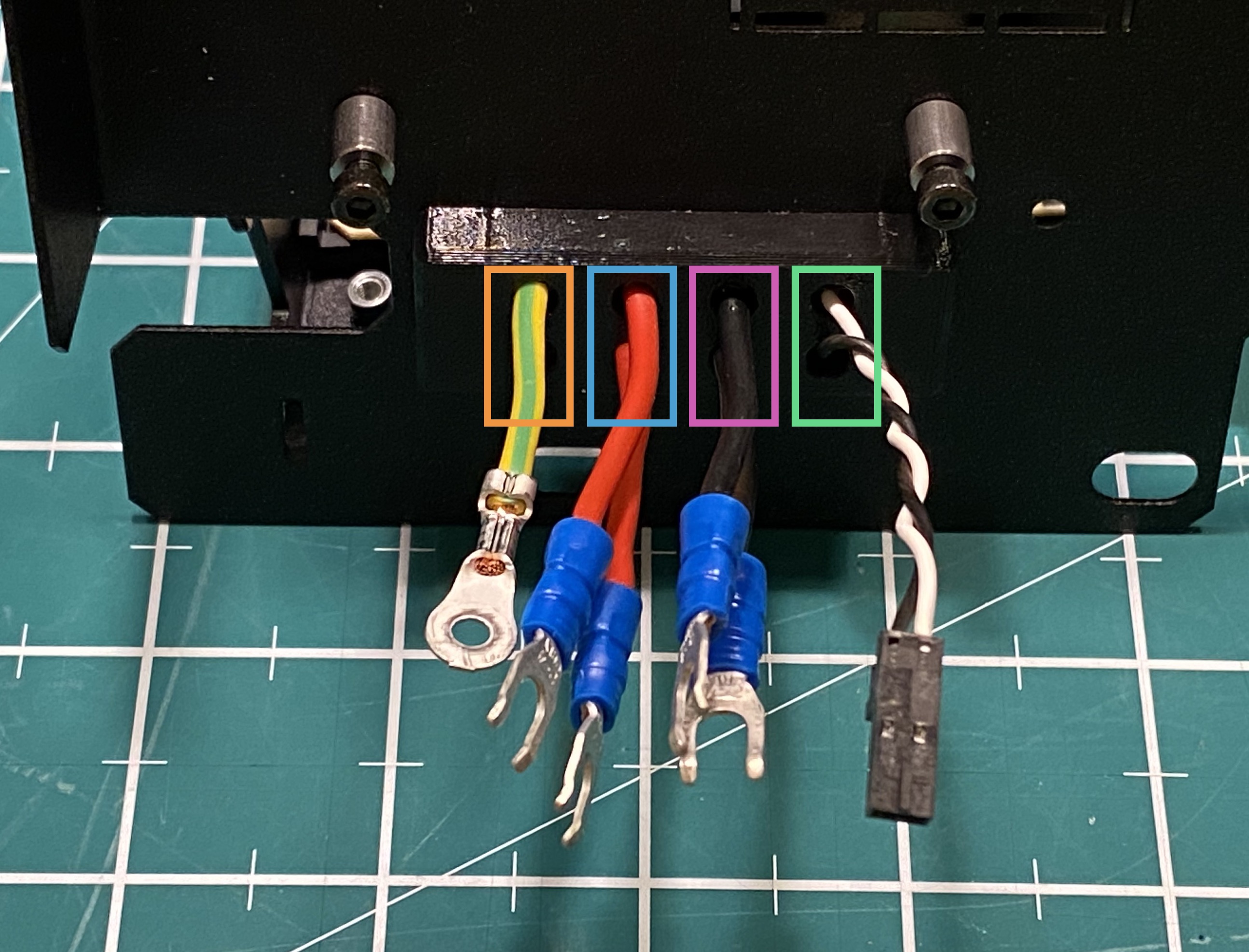
In all following Fotos I color coded the Wires :
- Orange = Earth/PE ( just one of two Pins is used )
- Blue = Positive 24V
- Purple = Ground
- Green = Power Panic ( Keep Track of the Polarity ! )

Cut the Wires accordingly to the following Foto. The lengths are rather short, so don't fall below the given Values. At the time I write this Manual, I recognized, that the Power Panic Wires in my Foto are not stripped like ( of corse ) they have to - sorry for that ;o)

“Poka Yoke” Feature
I designed the Connector with an integrated “Poka Yoke" Feature. This means, that the Connector can not be plugged in in the wrong Orientation. As bonus I Color coded the Ground Connection in Yellow. This is totally optional !

“Sandwiching” the Subunits
The “xxxCoverCap” is equipped with two M3nS Nuts (green).
2x M3x30mm Screws will be feed through the bores (orange) of the “MaleConnectorHolder” and the “xxxCoverHousing”.


I was lucky enough, to find two 3x20mm Pins (orange) in my Spare Part Bags. If you have just one Pin left over, you can use just one Pin, or leave the Pins out. They just provide alignment. Maybe give it a try to print those Pins ;o)

The XT60(H) Connector with the “Twist”
My Design uses the XT60H Connectors. This Connectors a meant to be used with a small Cover Cap. It turns out, that the Lip on the XT60H Connector fits just perfect in the Cutout of the PSU Mounting Bracket. The Connector needs just a little “Twist”, to go in there.

Once you “forced” the Connector into the Cutout, it will go in there nice and tight.
Securing the Female Connectors
After the XT60H Connectors are seated and fitted in the Cutout of the PSU Mounting Bracket, they can be “secured” by the use of the “FemaleConnectorHolder”. Now you can align the Subassembly with two M3x12 or 3x14 Screws to the Notches (green). The Screws go into the M3nS Nuts (orange) inside the “FemaleConnectorCover”. But wait! We need to solder the Cable Connections first !


Lets solder it !
I found it the easiest way, to remove the XT60H Connectors again from the PSU Mounting Bracket, in order to have better access when soldering the connections. Keep Track of the Orientation of your XT60H Connectors!
Keep in Mind, that the yellow one is rotated 180°, to implement the Poka Yoke Feature!
- Orange = Earth/PE ( just one of two Pins is used )
- Blue = Positive 24V
- Purple = Ground
- Green = Power Panic ( Keep Track of the Polarity ! )

Reassemble the “Power Supply Side”
After all Connections have probably been soldered, the XT60H Connectors with the short Wires can be feed through the Cutout in the PSU Mounting Bracket and "wiggled" back in Place like described earlier.
Install the Power Supply back to the PSU Mounting Bracket by the use of the original given Hardware.

Now Connect every Wire like they were before. Be sure to tighten, but not to over tighten the screws. “Click” the Power Panic Connector back in Place.

Put the PSU Cover back on … thats it for the PSU Part of this Project ! HARIBO Time ;o)

Pinter Bundle Side
For the Rest of this Manual I take a Shortcut … The corresponding wires of the “Printer Side cable bundle" need to be soldered to the “Male” XT60H Connectors accordingly. Don't forget to feed the Cables through the “xxxCoverHousing” before Soldering the Connections ! Also consider to add shrink tubes to your wires prior to solder them to the XT60H Terminals.

Bundle the Wires together with the textile sleeve and clamp them with the two halves of the “StraightCoverCaps” if you did choose the “straight” Connector, or by the use of the “AngledCoverCap”, if you have chosen the “angled” Connector. In both cases secure everything with a tie wrap.

Last Check prior to first Function Test
Double and tripple check that all Wires are matching the corresponding Connectors.
- Orange = Earth/PE ( just one of two Pins is used ) correct ?
- Blue = Positive 24V correct ?
- Purple = Ground correct ?
- Green = Power Panic ( Keep Track of the Polarity ! ) correct ?


Plug and Pray ;o)
Now it's Time to plug the Quick-Connector in for the first Time. My XT60H Connectors went together rather tight, but this way I can be sure, the connection will not come loose by it self.


Done !
Congratulations! You made your self a XT60H PSU Quick-Connector. Feel free to eat as much HARIBO's as you want - Happy printing and quick-connecting!