
manual 2-speed gearbox
Obliczymy ostateczną cenę na podstawie wybranego pliku. Sprawdzisz ją i zaakceptujesz przed płatnością.
Zapisane na tym urządzeniu.

Manual 2-speed gearbox.
- Ocena
- 0 / 5
- Polubienia
- 19
- Pobrania
- 102
- Wydruki
- 0
- Wyświetlenia
- 1296
- Oceny
- 0
Aktualizacja u źródła:
Informacje o modelu
- Źródło
- Printables
- Kategoria
- Mechanical Parts
- Licencja
- Creative Commons — Attribution — Share Alike
Simple 2-speed manual Gearbox.
To assemble you need 8x m3x10 screws
Material: PLA
It takes about 150g of Filament.
The following parts require supports:
- Switching unit
- countershaft
- housing main
Slicing instructions:
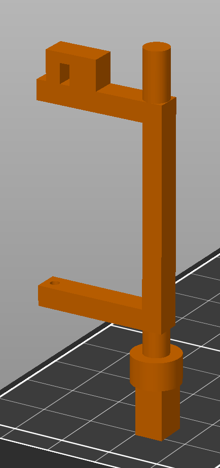
You have to rotate the switching unit like this on the print plate.
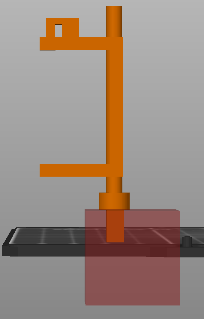
And put a support-blocker like this.
Assembly-instruction:
Step 0:
Required parts for the assembly:

Step 1:
Parts needed:

- pinon shaft
- clip 2
Assembly instruction:

Put the clip over the pinon shaft, like shown in the picture.
Step 2:
Parts needed:

- Already assembled shaft
- gear 2nd gear
Assembly instruction:

Put the gear over the shaft, until it can't go any further.
Step 3:
Parts needed:

- pre-assembled shaft
- clip 3
Assembly instruction:


Put the clip over the shaft, until it clicks, just over the gear for the 2nd gear.
Step 4:
Parts needed:

- gear shift disk
- pre-assembled shaft
Assembly instruction:

Put the gear shift disk over the shaft.
Step 5:
Parts needed:

- pre-assembled shaft
- gear 1st gear
Assembly instruction:

Put the gear over the shaft.
Step 6:
Parts needed:

- pre-assembled shaft
- clip 4
Assembly instruction:

Put the clip over the shaft until it clicks.
Step 7:
Parts needed:

- switching unit
- switching shoe (2x)
Assembly instruction:

Put the switching shoes into the small holes on the switching unit.
Step 8:
Parts needed:

- pre-assembled shaft
- pre-assembled switching unit
Assembly instruction:

Put the switching unit with the shoes over the gear shift disk.
Step 9:
Parts needed:

- housing main
- pre-assembled shaft
Assembly instruction:

Put the pre-assembled shaft into the housing like in the picture.
Step 10:
Parts needed:

- pre-assembled housing
- countershaft
Assembly instruction:

Put the countershaft into the housing like shown in the picture.
Step 11:
Parts needed:

- pre-assembled housing
- housing cover
- 4x m3x10 screws
Assembly instruction:v

Put the housing cover on the housing like shown in the picture.

Put the 4 m3x10 screws in like in the picture shown.
Step 12:
Parts needed:

- Pre-assembled housing
- switching unit holder
- 2x m3x10 screws
Assembly instruction:

Put the switching unit holder over the switching unit and put the screws in the holes on the side.
Step 13:
Parts needed:

- Pre-assembled housing
- shift lever
- 1x m3x10 screw
Assembly instruction:

Put the lever over the switching unit and screw it tight with the m3x10 screw.
Step 14:
Parts needed:

- pre-assembled housing
- crank main
- crank handle
- clip 5
Assembly instruction:

First put the crank handle into the hole in the crank main.

Then put the click over the crank handle.

Finally put the crank handle on the countershaft and screw it tight with the m3x10 screw.
Step 15:
Parts needed:

- Pre-assembled housing
- clip 1
Assembly instruction:

Put the clip over the pinon shaft.
Optional:
You can design your own attachements for the pinon shaft by designing a hexagon with an inner circle with the diameter of of 6mm and an extrusion of 4mm.