
"Limited Slip" Torsen differential Type 2
Obliczymy ostateczną cenę na podstawie wybranego pliku. Sprawdzisz ją i zaakceptujesz przed płatnością.
Zapisane na tym urządzeniu.

Limited Slip Torsen Differential Type 2
- Ocena
- 5 / 5
- Polubienia
- 58
- Pobrania
- 328
- Wydruki
- 1
- Wyświetlenia
- 2831
- Oceny
- 1
Aktualizacja u źródła:
Informacje o modelu
- Źródło
- Printables
- Kategoria
- RC & Robotics
- Licencja
- Creative Commons — Attribution — Noncommercial — Share Alike
UPDATE 20240422:
The Housing connector are not designed well and break easily. Stand tight while I work on something better.
Description:
While I was looking for a solution to prevent spinning wheels for my planned RC Crawler, I wanted to understand the different ways of how Limited Slip Differentials would work and especially the Torsen variant.
I came across a good Youtube video and the model of @idlebear_108087 , and after loading and understanding the principles helped me develop my own, in a as small as possible size (it is still not small, to cope with the forces involved).
So the mechanical principle is that on the inside there are pairs of helical gears which are pushed to the outside diff housing, whenever a wheel is free spinning hence creates friction and forces the other axle to turn as well. (at least that is what i understood).
Hence my example is working but as the Helical Gears have low surface area will not lock extensively. The plan is to make this a Torsen diff with the option to fully lock the diff via a servo either way, as Torsen diffs Type 2 are not particularily suitable for offroad driving.
The LS Diff comes without need to screw anything, however a production unit would need some changes in the housing. the inner values count and work without any screw.
It includes 3 sets of helical gears on the inside to be more resistent against the load forces.
Assembly:
- Mount the longer (right side) axle with the 18 tooth helical gear into the Ring Gear. Secure with a C-Clip. The Clip should be flush with the housing (+0.2-0mm)

- Mount small helical gear pairs into the Ring Gear. Direction: there is a smaller Axle end, which always has to face the Ring Gear side. Make sure the helical gears, which have the helix on the bottom, are in the slot where the holes are, so the Ring Gear lid can be inserted:
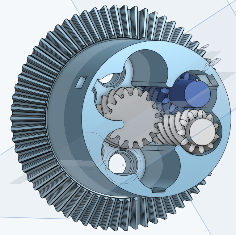
- Mount the remaining helical gears and add Ring Gear lid w. left axle and C-Clip installed.
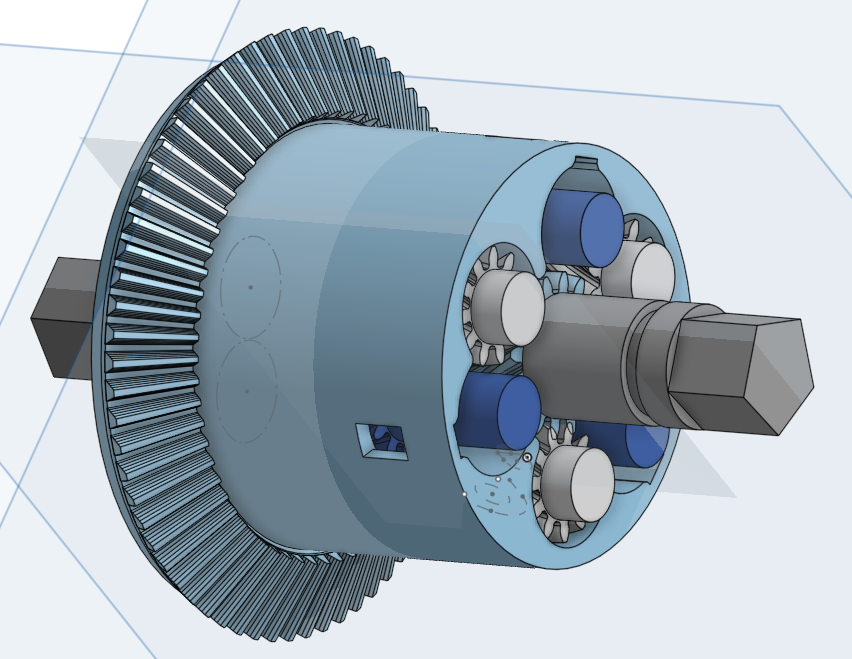
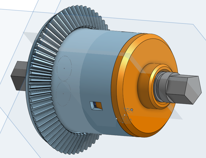
- Add the Driveshaft into the Housing and secure with a C-Clip
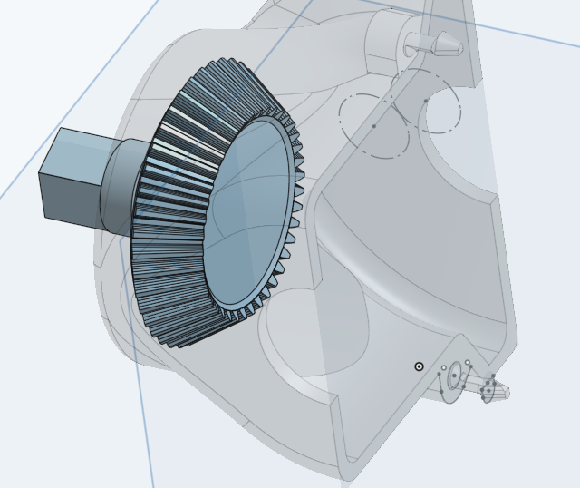
- Close the Housing
- Add the completed diff onto the Stand (optional).
