
DexCal - Extruder Offset Calibration with Unlimited Precision
Obliczymy ostateczną cenę na podstawie wybranego pliku. Sprawdzisz ją i zaakceptujesz przed płatnością.
Zapisane na tym urządzeniu.

A parametric calibration print to fine-tune your dualstruder.
- Ocena
- 0 / 5
- Polubienia
- 6
- Pobrania
- 16
- Wydruki
- 0
- Wyświetlenia
- 304
- Oceny
- 0
Aktualizacja u źródła:
Informacje o modelu
- Źródło
- Printables
- Kategoria
- Test Models
- Licencja
- Creative Commons — Attribution
Theory
The idea behind this calibration is to give you an unambiguous and precise measurement of your extruder offset by testing where the samples will fuse. For instance, if a sample fuses to the right but not to the left, that means the second extruder is too far to the left. By printing multiple samples with different gap sizes, we can easily calculate exactly how far to the right we need to offset it.
Instructions
Rough Calibration
Before you use the DexCal, I'd recommend doing a rough calibration using a simpler approach, such as a square inside a frame. While you could make samples with huge gaps, DexCal is primarily designed for fine tuning.
Finding Your Tolerance
Use my Tolerance Test to find the tolerance t of a single extruder. This step isn't strictly necessary but will help you set better values for your first DexCal print. Testing one extruder in one axis should be enough unless you suspect large deviations (in which case, calculate the average, I guess).
https://www.printables.com/model/906256-tolerance-test-for-dexcal
Generating Calibration Objects
Blender
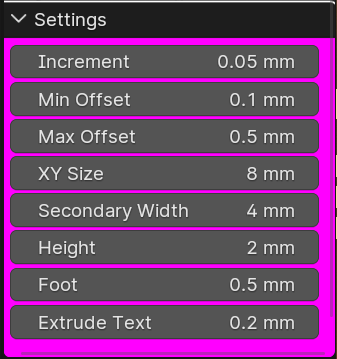
Open DexCal.blend in Blender 4.1 or later. (No Blender experience required.) Find the Settings menu. (I made it magenta so you can't miss it!)
You will only need to change the top three settings. (You can hover on the others if you're curious.)
Increment sets how much the gap will increase with each step. This determines the precision of your calibration.
Min Offset sets the gap in the first sample.
Max Offset sets the gap in the last sample.
Guesstimate your current maximum offset error e (too big is better than too small). For instance, if you're willing to bet that neither axis is off by .5mm or more, your e should be .5. Set Min Offset to t - e and Max Offset to t + e.
Exporting a Calibration Object
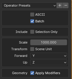
Once you're happy with your settings, go to File → Export → STL (.stl). In the menu to the right in the export window, make sure Batch and Apply Modifiers are checked and Scale is set to 1000. Navigate to the folder where you want to save your object and hit Export STL.
When you've exported a new version, do not right click the object in the slicer and hit Reload from disk as this can cause misalignment. Instead, delete it and import the new one.
Reading Your Print
Remove the samples from the bed. There should be at least one sample where all the tabs have fused to the center block and at least one where none have fused. If there's no sample with four tabs, decrease your Min Offset. If there's no sample without tabs, increase your Max Offset. Once your print satisfies the above criteria, it's time to do the math and change your offsets.
DexCalc

- In DexCalc.odt, set Increment, Min Offset and Max Offset to match your Blender settings.
- Set n0x to the lowest number without a tab in the positive X direction and n1x the lowest without a tab in negative X.
(In my case, left is positive on the SV04, so n0x = 6 and n1x = 2.) - Set n0y and n1y equivalently for Y.
- Adjust your extruder offsets by Δx and Δy respectively.
(As you can see, my Y offset is a bit too far off as I still have a top tab on the last sample. It seems about as firmly attached as the bottom tab on sample 0 so I'll just assume that n0 = 1 and n1 = 9 and hope the next print will sort this out.)
Repeat according to the instructions below until you reach the minimum increment of your printer's offset setting. You may want to repeat the last print just to verify. If n0=n1 in both X and Y, it's spot on. If you can't quite achieve this, that's probably because the real world is stupid. Your offsets should be very exact regardless.
Settings for Next Iteration
Provided that your first iteration was a success, here's how to set appropriate values for the next iteration
- In Blender, set Min Offset and Max Offset according to the next line in the spreadsheet.
- Decrease Increment until you get a reasonable number of samples.
The Future
Features and Stuff
There are some features that would be nice to implement but I probably won't consider them worth the time. Here's a list in case you'd like to help:
- Automatically split the samples into multiple rows according to a max width, in case you want to print many samples on a small bed.
- Separate X and Y options for Increment, Min Offset and Max Offset.
- The option to only calibrate X. (You could rotate in slicer to only calibrate Y.)
- Better centering. The object isn't perfectly centered in X but this is a slight annoyance at worst.
If you make this project unambiguously better, I'll probably implement your changes here and give you credit, in order to avoid different versions with different benefits.
Feedback
Instructions unclear? Too long? Incorrect? Ugly colors in my node setup? I love feedback, so don't hesitate to let me know how this project can be improved. I might make a video if enough people are interested in that.
Please let me know if my math worked for you and what level of precision you managed to achieve!