
Shelly Housing (1-/1PM-/PM-Mini)
Obliczymy ostateczną cenę na podstawie wybranego pliku. Sprawdzisz ją i zaakceptujesz przed płatnością.
Wstępna wycena dla PETG
1,06 € – 1,30 € netto (bez VAT)
Dla pliku: shelly-pm-mini-housing_0.4n_0.2mm_PETG_MINIIS_1h0m.gcode
To wstępna wycena jednego pliku. Dokładną cenę poznasz przed zamówieniem.
Plik i założenia wyceny
Plik użyty do wyceny
Średnia wycena orientacyjna: 1,18 € netto (środek widełek).
- Masa podana przez autora
- 20 g
- Czas druku podany przez autora
- 59,4 min
- Materiał u źródła
- PET
- Materiał wyceny
- PETG
- Drukarka wyceny
- Bambu Lab P1S - 0.4 nozzle
- Proces wyceny
- 0.20mm Standard
Orientacyjna wycena wyłącznie wybranego pliku, oparta na masie i czasie druku podanych przez autora. Warianty plików nie są sumowane. Ostateczna cena zostanie obliczona po analizie pliku.
Zapisane na tym urządzeniu.

Compact housing with minimal hardware, optimized printability, and easy wall mounting.
- Ocena
- 5 / 5
- Polubienia
- 87
- Pobrania
- 489
- Wydruki
- 8
- Wyświetlenia
- 3198
- Oceny
- 7
Aktualizacja u źródła:
Informacje o modelu
- Źródło
- Printables
- Kategoria
- Electronics
- Licencja
- Creative Commons — Attribution — Share Alike
Disclaimer: Be aware that in many jurisdictions, mains voltage installations must only be executed by qualified or even only certified individuals! This model description as well as the attached pictures are only for demonstration purposes. For installation instruction and wiring diagrams, consult Shelly's official documentation.
Additionally Required Hardware
Item | Quantity |
|---|---|
WAGO 221-413 (3-conductor) | 2 |
M3×12mm Socket Head Screws (DIN 912) | 2 |
Optional: Zip Ties* | 2 |
Cable, Plug and Socket |
|
* I strongly suggest implementing some sort of strain relief. Use either zip ties or the provided strain relief ring. The latter can be fixed to the cable using super glue.
Compatible Devices
The following table includes devices that have been posted as Makes. This is not an exhaustive list; other devices may be compatible.
Gen3 Device | Tested by |
|---|---|
FH | |
Gen4 Device | Tested by |
|---|---|
Features
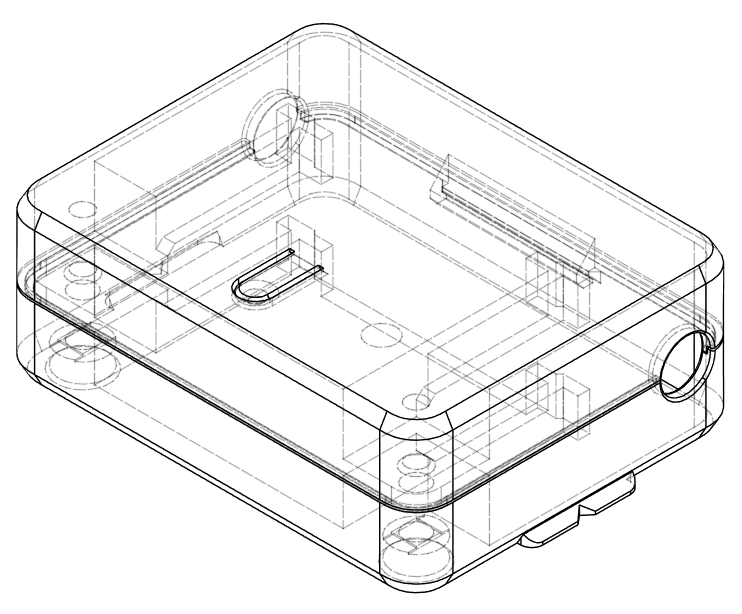
This case was developed to address common issues I found in existing designs, such as unnecessary bulk and excessive hardware requirements. The design incorporates several key features aimed at optimizing functionality and ease of assembly. Below is an overview of the primary design elements, including a clamp-based closure to minimize the need for metal fasteners, a wall-mounting clamp for straightforward installation, and provisions for LED and button accessibility—all while ensuring printability with careful attention to overhangs and bridges.
Closing Features
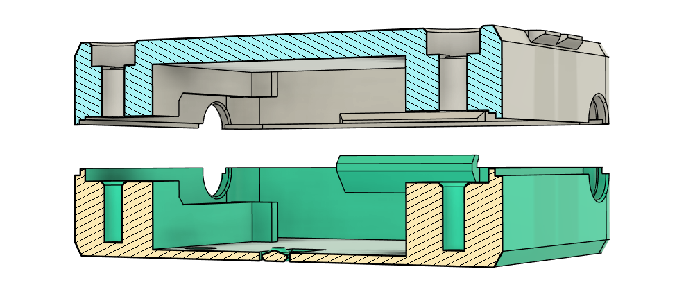
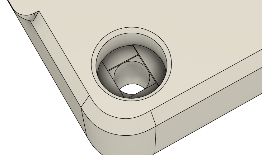
Compared to similar models, the closing mechanism of this design is reduced to the absolute minimum necessary. The top half is secured with just two screws and a latch on the opposing side. While other designs may use heat-set inserts—which indeed look impressive on 3D-printed parts—this model opts for 2.7 mm holes. This size provides sufficient grip for an M3 screw, allowing for direct installation without any pre-processing.
Wall Mounting Clamp
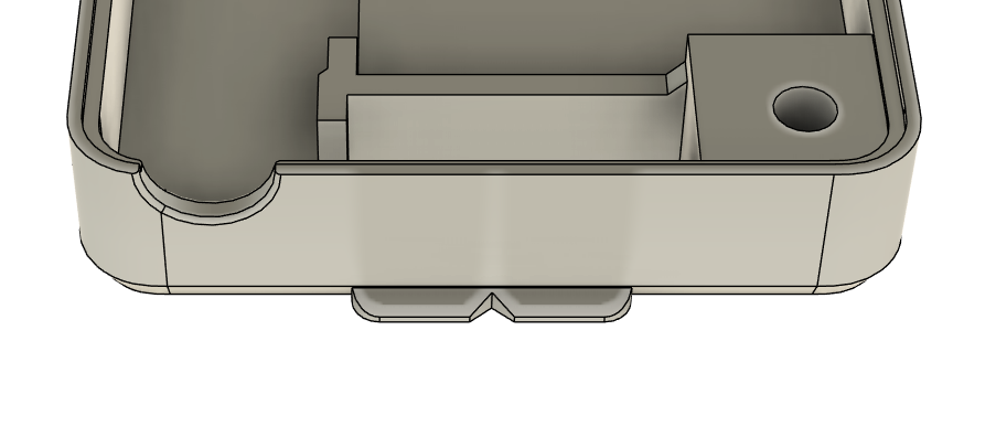
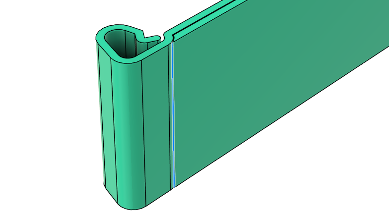
During testing, I quickly realized the need for a simple yet effective fixture—a clamp that securely holds the box in place at its final destination without complicating the installation process. The clamp can be easily attached to a wall using tape and grips onto the indexing features at the bottom of the housing.
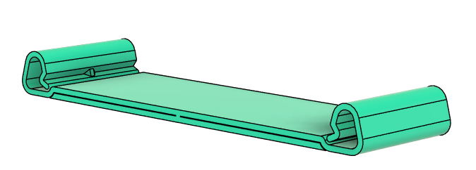
To address the challenges of printing thin walled compliant structures, such as the springs on the clamp, the design has been optimized for vase mode. This allows the entire clamp to be printed as a continuous extrusion path, reducing the need for manual adjustments to seam positions. The model is designed for use with a 0.4 mm nozzle and corresponding line width.
Printability
The design of this model prioritizes ease of printing, with all overhangs angled at 50 degrees or more, which is generally considered a safe overhang in PrusaSlicer. For any areas with 0-degree overhangs, they are specifically designed to be easily bridged, ensuring a smooth printing process without the need for additional supports.
Compact Design
Through multiple design iterations, I have reduced the outer dimensions of this housing to an optimal size. The width is dictated by the space needed for two WAGO clamps and the Shelly PM Mini, along with the necessary walls in between. The height and depth have also been carefully minimized while ensuring all components fit securely.
Operability
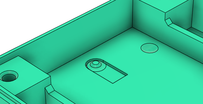
For full operability, the design includes a thin section to allow LED visibility and a compliant segment that provides easy access to the button beneath.
Print Instructions
The compliant mechanism on the base will work best printed in PETG, but ABS or ASA will be fine as well. I advise against using PLA due to the potential heat generated by the PM Mini. PLA may soften, which is undesirable for a case containing mains voltage.
This model ist optimizes to be printed with a 0.4 mm nozzle. or the shell parts, you can use your default slicing profiles.
For the clamping bracket, I recommend using vase mode. Alternatively, if not using vase mode, place the seam in one of the bottom side corners to ensure a clean finish.
Assembly
Only attempt assembling this if you understand the risks involved with mains voltage!
For a detailed installation guide study Shelly's official documentation. My instructions here only cover the mechanical details.

Preparation
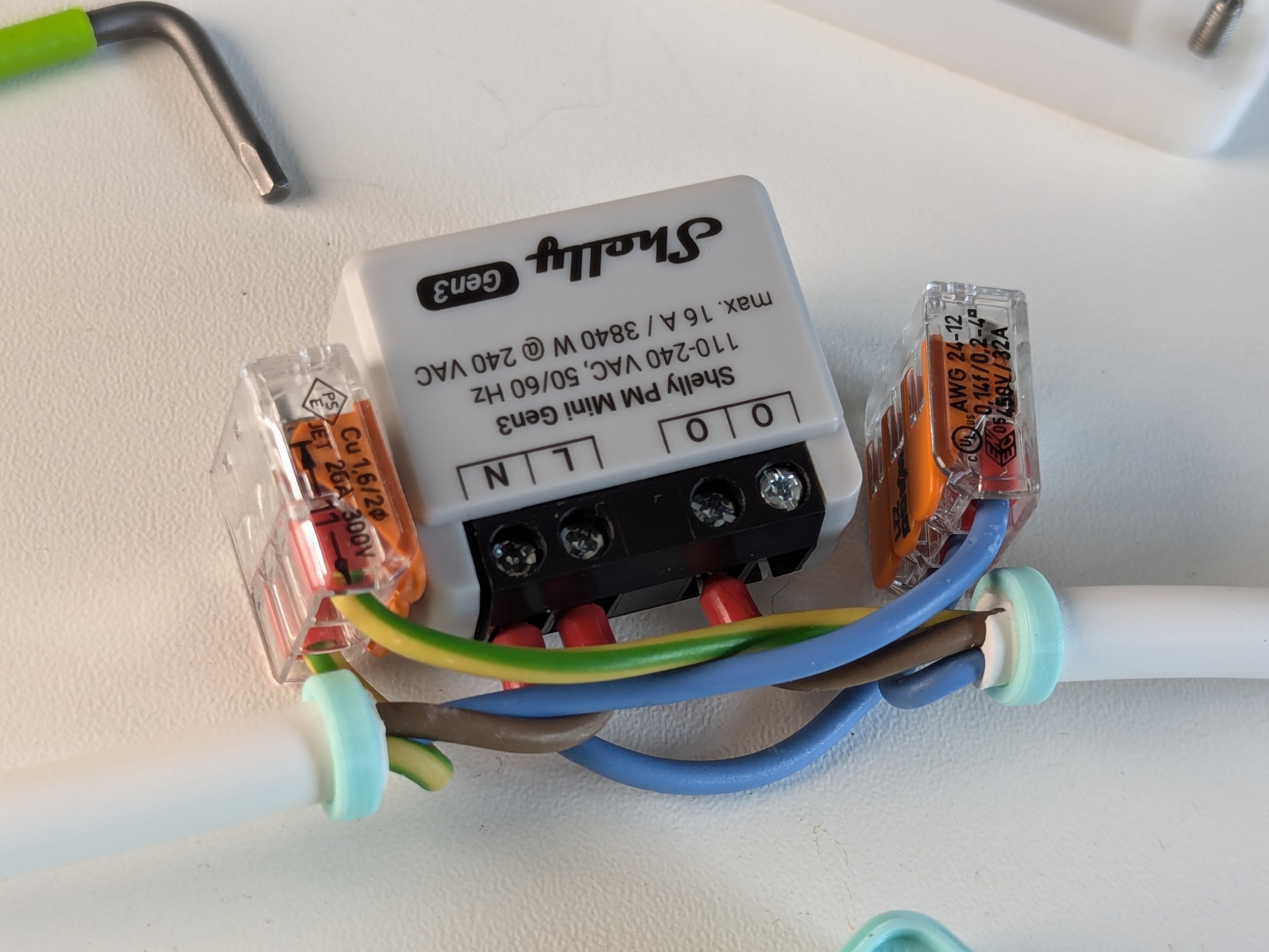
Given the limited space within the housing, precise wire lengths are crucial for a successful assembly. To simplify the process, I’ve outlined the necessary wire lengths below. You will need the cables for both the input and output connections, as well as an additional piece of blue wire to serve as the neutral line.
Length | Input Line | Output Line | Extra |
Neutral (N) | 66 mm | 36 mm | 70 mm* |
Phase (L) | 34 mm* | 34 mm | - |
Protective Earth (PE) | 46 mm | 76 mm | - |
*cut ~2mm off of one of the ferrule to make it fit into the screw terminal on the PM Mini
For a secure connection, I recommend using ferrules on all wire ends. Note that the ferrules may need to be shortened slightly to fit properly into the terminals on the PM Mini. Also consider WAGOs guide on using ferrules with 221 connectors.
Installation: PM Mini
Once your wires are prepared, follow this installation order:
Connect the input and output phase lines to the PM Mini.
Connect the separate neutral line to the PM Mini.
Bend the short PE and N wires around their respective cable axes and secure them in the WAGO clamps.
Connect the PM Mini's neutral line to the corresponding WAGO clamp.
Connect the long PE and N wires.
Finally, place the WAGO clamps into the bottom housing. While inserting the PM Mini, push the wires below the latch to ensure a secure fit.
Installation: 1PM Mini
DJ took the time to create a schematic diagram of the wiring for the 1PM Mini. Find it in the comment section. The installation is carried out in the same way as described above.
Remarks
I don't provide a clamp version with a screw hole because I think it's a bad idea to drill holes close to power outlets.
Alternativ Solutions
Shelly Plug S - If you have the space it's much easier to just buy the Shelly socket proxy piece, it does power metering as well and additionally let's you turn off the outlet.
Shelly 1 PM mini housing by Reedy The inspiration and original solution to the problem I tried solving here. I had some changes in mind that I wanted to implement so I developed my own versionShelly
Mini Smart extension cable housing (no Screws) by jju182 A similar approach that doesn't use any screws.