
M20 x 2.5 printed thread allowance/offset test [Fusion 360 source file included]
Obliczymy ostateczną cenę na podstawie wybranego pliku. Sprawdzisz ją i zaakceptujesz przed płatnością.
Zapisane na tym urządzeniu.

Model to test required offset to apply when designing parts with printed threads
- Ocena
- 0 / 5
- Polubienia
- 2
- Pobrania
- 64
- Wydruki
- 0
- Wyświetlenia
- 377
- Oceny
- 0
Aktualizacja u źródła:
Informacje o modelu
- Źródło
- Printables
- Kategoria
- Test Models
- Licencja
- Creative Commons — Attribution
Reduce filament and time waste on printing non-matching threads in designs which include 3D printed threads!
My approach is to model internal thread and add offsets only to external thread - this is based on my experience where externally threaded “screw” components are smaller and easier to reprint than parts with internal threads, but if you test required tolerance on those test pieces, you'll know how much offset to apply in your target designs.
- Import .step file to your slicer and slice it with settings you will be using when printing your target model.
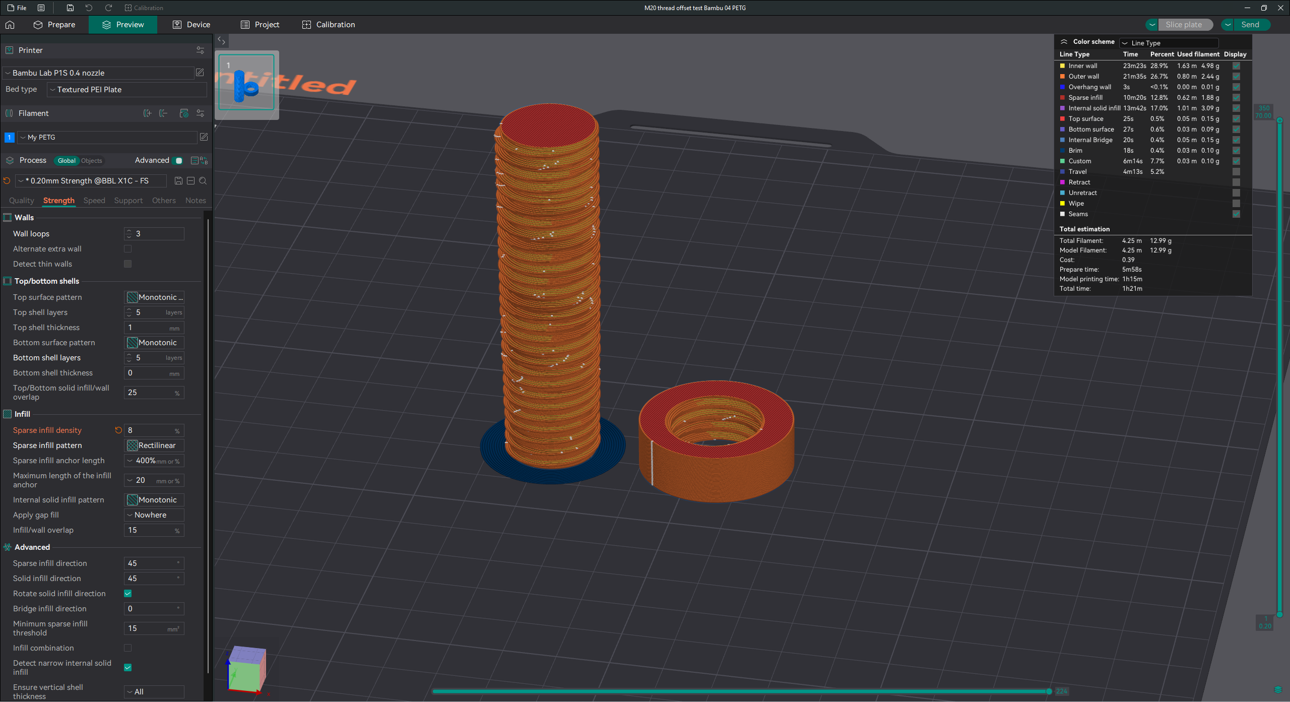
- Print the parts.
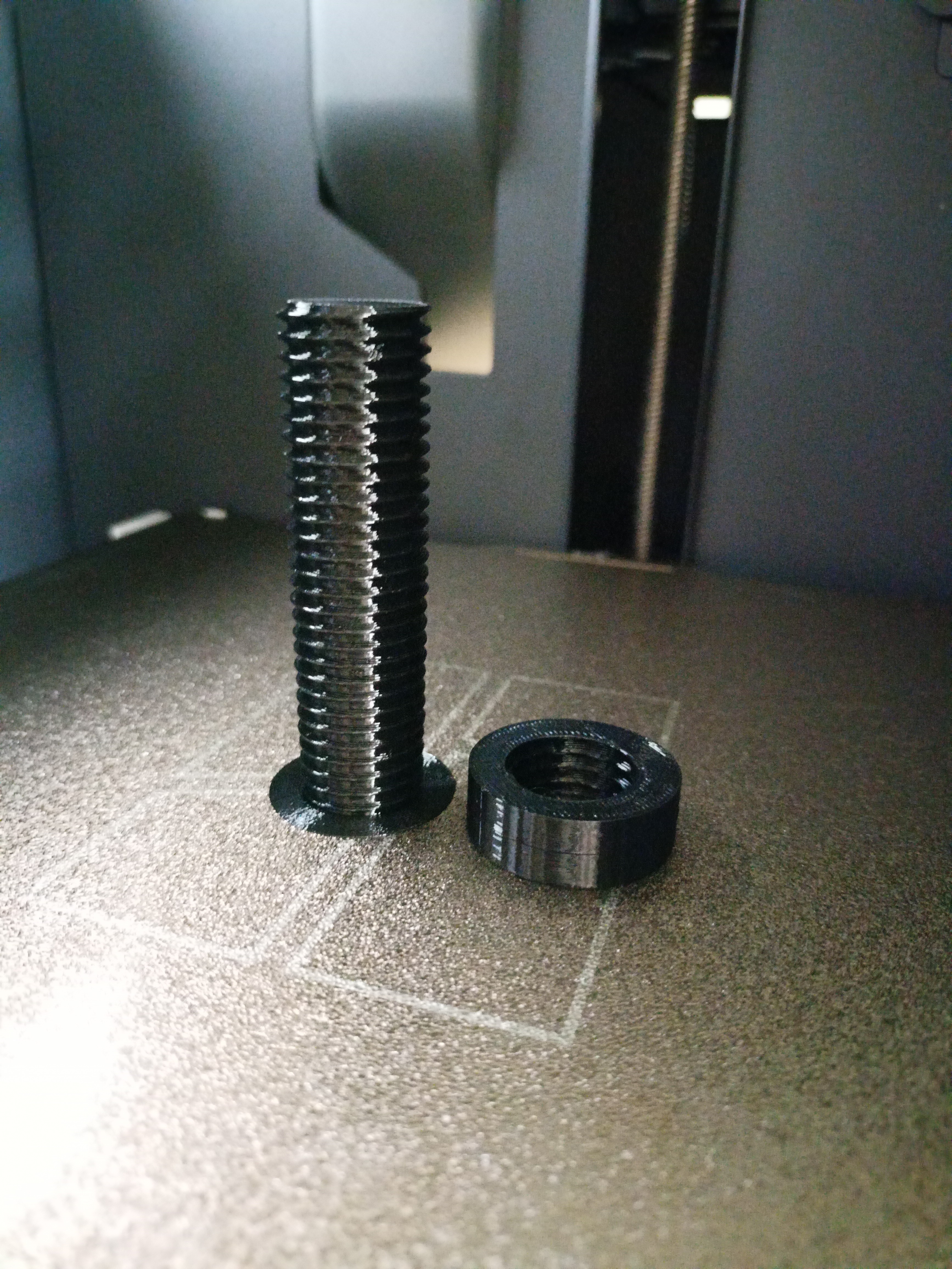
- Start screwing the “nut” from the bottom part of the screw where thread is the thinnest.
- Measure position in which the nut is not wobbly, but not too hard to turn.
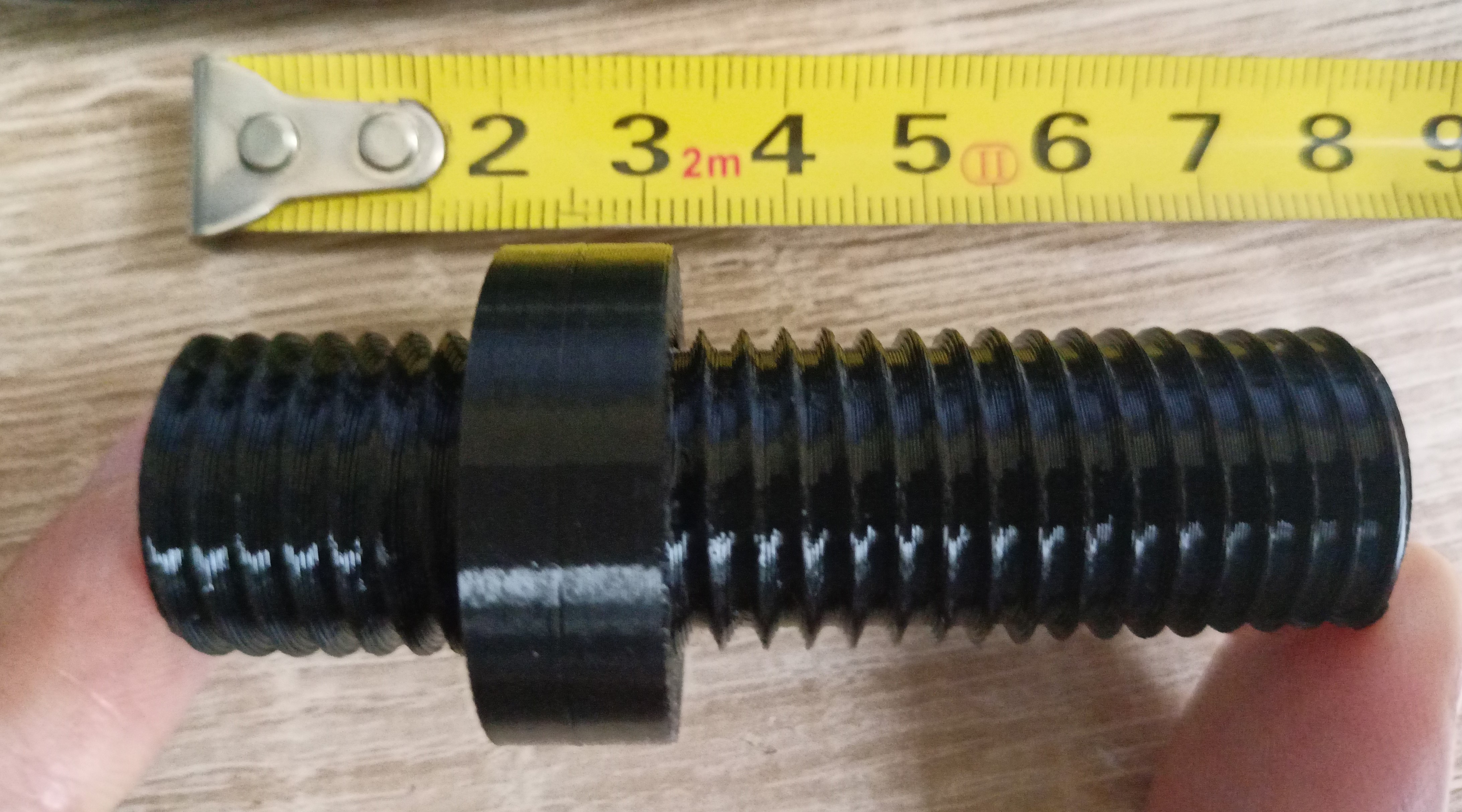
- Check offset for segment of your choice. In my case it's third one counting from the top, which corresponds to -0.10 mm
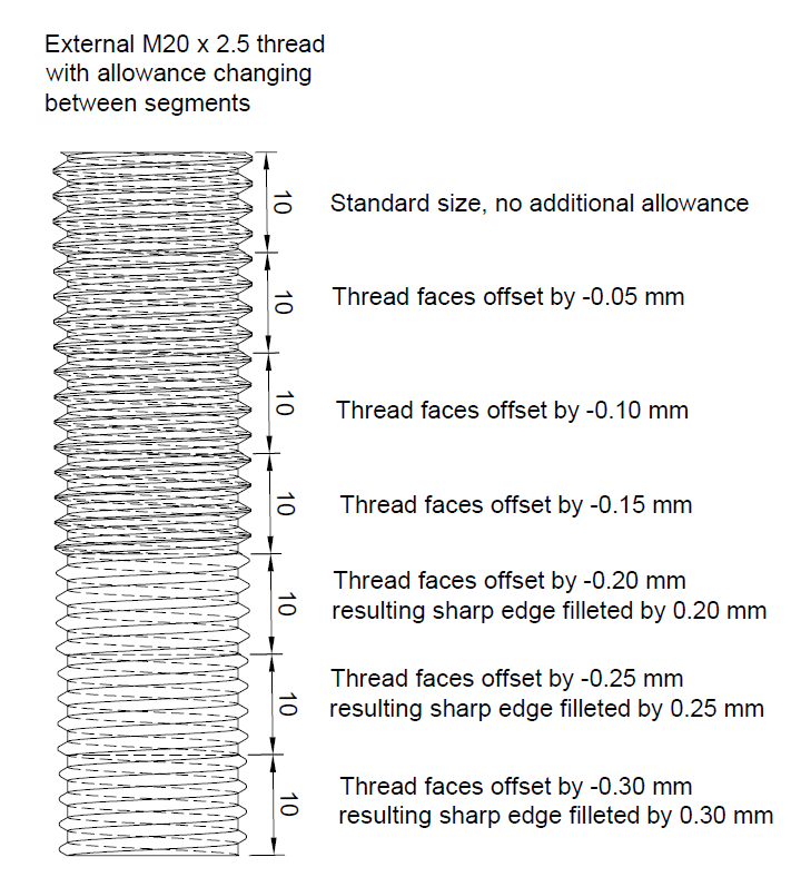
- In your target design model an internal thread of the same size without any changes.

- Apply external thread to the screw part.
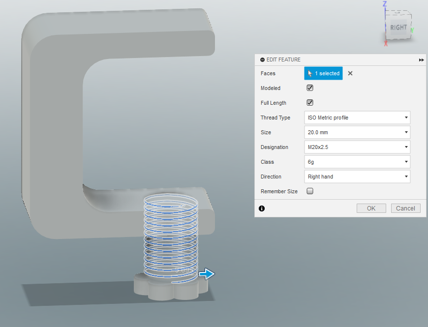
- Offset all three faces of the thread: both angled faces first and flat external one at the end using value you obtained with test model.
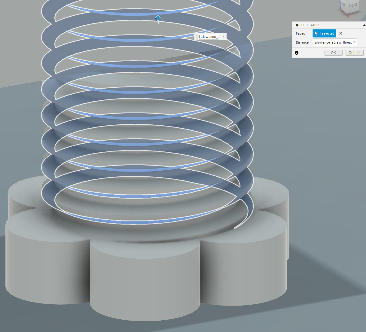
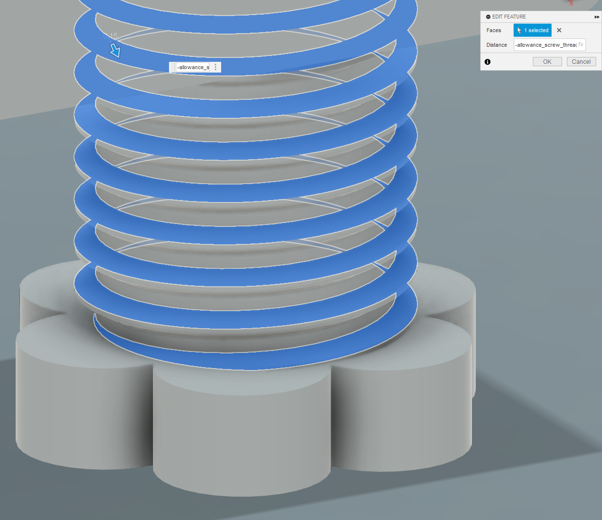
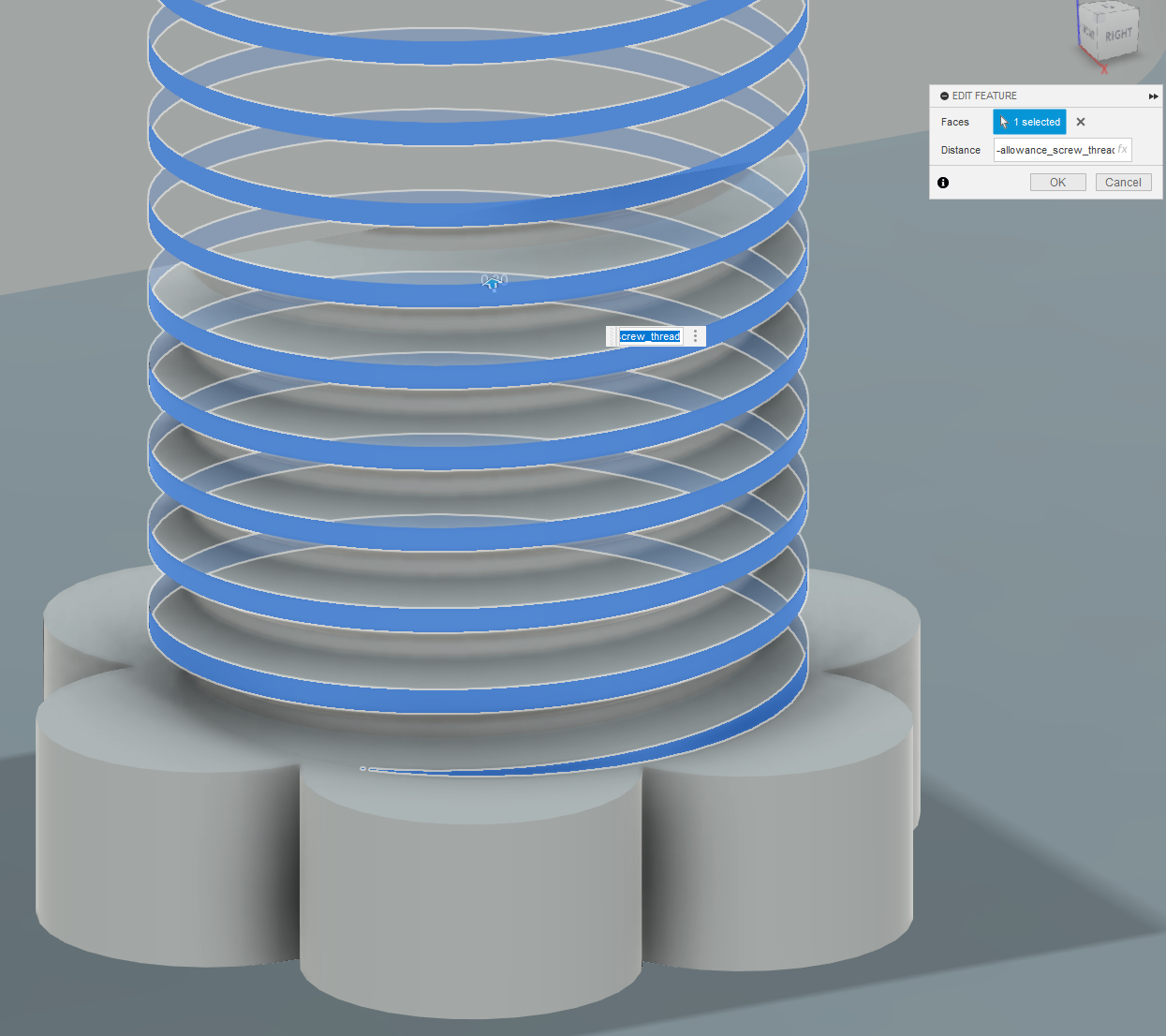
NOTE: if your printer requires bigger tolerances to be used, then after applying offsets to upper and lower angled faces of the thread, it's external flat surface collapses to single edge.
In case of this M20 thread test model, this happens for offsets larger than 0.15 mm - in other words, bottom three segments have rounded edges. Just use the same “press pull” function, which will apply a fillet to this edge.
To see how it's done, you can import .f3d file into Fusion360 and jump through the timeline to check out how I did it, and recreate this offset strategy in your design.