
PSU Relocation Bracket and Relay Enclosure for Ender 3 Printers
Obliczymy ostateczną cenę na podstawie wybranego pliku. Sprawdzisz ją i zaakceptujesz przed płatnością.
Zapisane na tym urządzeniu.

Relocate the (Cheng Liang P360W24v) Ender 3 power supply, relocate the IEC power inlet, and house a relay board.
- Ocena
- 5 / 5
- Polubienia
- 22
- Pobrania
- 182
- Wydruki
- 2
- Wyświetlenia
- 1039
- Oceny
- 1
Aktualizacja u źródła:
Informacje o modelu
- Źródło
- Printables
- Kategoria
- Creality Parts & Upgrades
- Licencja
- Creative Commons — Attribution — Noncommercial — Share Alike
PSU Relocation Bracket and Relay Enclosure for Ender 3 Printers
Modeled to accommodate the stock Cheng Liang P360W24v Power Supply
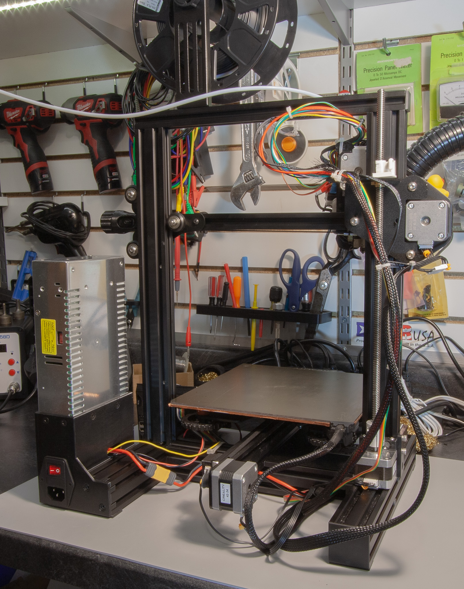
This part is designed to accomplish the following on an Ender 3:
Provide clearance for dual-Z-axis mods (works with Kevinakasam's belt mod)
Relocate the stock IEC power inlet towards the rear of the printer
Provide a mount/enclosure for a relay module (no affiliation.)
In addition, the design is optimized to:
Interface snugly with the Ender 3's v-slot extrusions (you might need a hammer)
Add no height, width, or depth to the stock printer (as a cuboid)
Be printable with practically no supports (see slicer recommendations)
Use Ruthex threaded inserts wherever possible (no affiliation)
If you'd like to mount a different board than the relay module linked above, know that the center-to-center spacing of the board standoffs are 66.5 x 34.8mm.
Parts Needed:
Hardware: | Note: | Quantity: |
|---|---|---|
M5 Machine Screw, Button Head | Bracket to 4040 V-Slot Extrusion | 2 |
M4 x 8 Machine Screw, Countersunk | Enclosure to PSU | 5 |
M3 x 8 Machine Screw, Countersunk | IEC Inlet to Enclosure | 2 |
M2 x 8 Machine Screw, Countersunk | Enclosure rear cover | 4 |
M2 x 8 Machine Screw, Cap Head | Enclosure rear cover | 1 |
M3 Threaded Bushing (Ruthex) | IEC Inlet mount, Relay module mount | 6 |
M2 Threaded Bushing (Ruthex) | Enclosure rear cover mount | 4 |
Tools and Installation:
I won't explain how to transplant the power supply itself or deal with any of the electronics here. Working on anything that connects directly to mains (like a power supply) can be hazardous, and requires a level of knowledge that I cannot impart upon beginners through this medium. If you want help with the low-voltage side of things, consider a subreddit like r/AskElectronics.
In addition to the obvious hex keys, you will need a soldering iron with a conical tip to gently push each insert into place at 240-300°c (into PETG.) Any plastic squeeze-out can be trimmed flush with a razor blade.

You may also find that you need a hammer in order to fully insert the (integrated) v-slot mounting bracket the final centimeter or so of travel. If you do, move the power inlet aside to avoid damage, and tap the enclosure home. Use a block to more evenly distribute the force and avoid denting the part. Bias force towards the longer of the v-slot channel inserts, but don't neglect to tap the (comparatively fragile) others. If you must, you can cut off the shorter inserts entirely; they really only exist to stand-in for the two M5 mounting bolts.
If your printer is like mine, you may find that unlike in the front, the back of the 4040 extrusion is not tapped for M5 machine screws. The obvious remedy here is to finish the job with an M5 tap. If you're not up for that, the interference fit of the v-slot channels is likely more than enough to compensate.
The rear cover has a notch with a small diameter hole that corresponds with a hole on the main body. This hole receives the one M2 cap head screw, which threads directly into the plastic. The hole will likely print undersized, and should be enlarged with a 1/16" or 1.6mm drill bit.
Printing:
Filament:
This part should be printed with a material that is reasonably tough, flexible and somewhat heat tolerant. I would highly recommend PETG, and discourage the use of PLA.
Orientation:
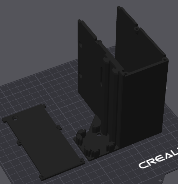
The main body of the enclosure should be oriented such that the rectangular IEC inlet cutout lies flat on the buildplate. The rear cover should be oriented such that its countersinks face upwards.
Suggested Slicer settings:
(These are not rules; just suggestions. Nomenclature per OrcaSlicer)
Quality:
Nozzle = 0.4mm
Layer height = 0.12mm (I found that a lower setting makes for better v-rail fitment)
Precision:
Precise wall = Enabled
Polyholes = Enabled
Polyhole twist = Enabled
Precise Z height = Enabled
Strength:
Wall loops ≥ 2
Sparse infill density ≥ 40%
Top shell layers ≥ 7 (default)
Bottom shell layers ≥ 5 (default)
Seams:
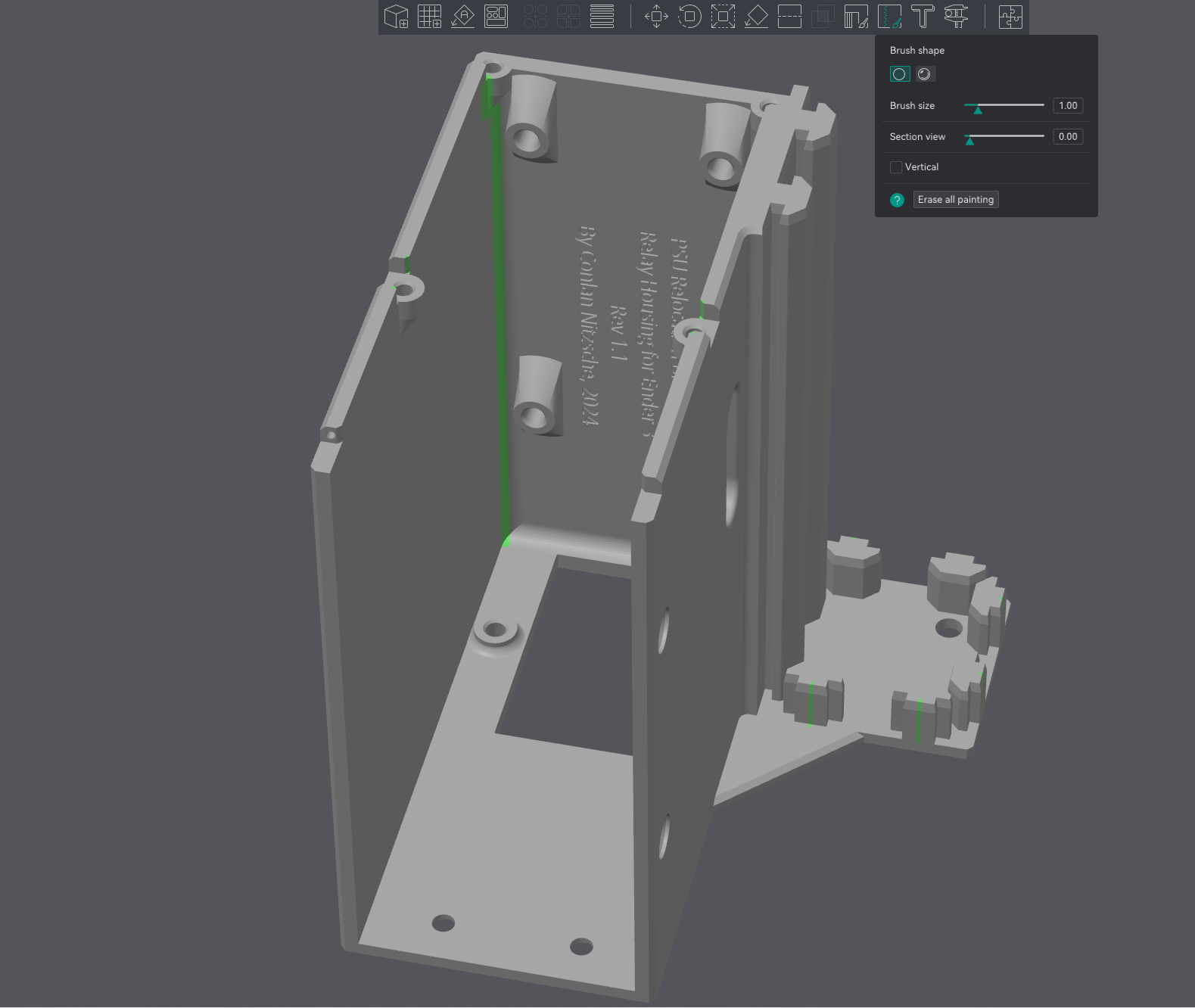
I used “aligned” seams, as well as the “seam painting” tool to place seams away from mating surfaces wherever possible. The main Z seam is best hidden somewhere inside the enclosure rather than on the v-slot guides. Where the rear cover interfaces with the main body, seams are best placed on the chamfered corners.
Support:
The two large counterbored holes facing the build place require supports. This can be easily achieved by enabling “Normal” supports, as well as allowing them “On build plate only.”


Remember to account for shrinkage if you want an accurate part! I had to scale the print to 100.6% on the X and Y axis in order to achieve accurate dimensions with my given printer and filament. In OrcaSlicer, shrinkage compensation can be saved in any given filament profile.