
Smaller SpaceMouse with Hall Effect Joysticks, PCB Wiring and BALLS OF STEEL!
Obliczymy ostateczną cenę na podstawie wybranego pliku. Sprawdzisz ją i zaakceptujesz przed płatnością.
Zapisane na tym urządzeniu.

3D printed balls replaced with steel ball bearings in steel guides. Hall Effect joysticks used. 80mm square X 90mm tall
- Ocena
- 5 / 5
- Polubienia
- 159
- Pobrania
- 531
- Wydruki
- 5
- Wyświetlenia
- 6045
- Oceny
- 6
Aktualizacja u źródła:
Informacje o modelu
- Źródło
- Printables
- Kategoria
- Computers
- Licencja
- Creative Commons — Attribution — Noncommercial — Share Alike
Having ball bearings running in metal sleeves results in a smooth action and a more compact SpaceMouse.
Hall effect joysticks eliminate dead zones and enable much finer control.
The only issue you need to be aware of is manufacturing tolerances in the 8mm ball bearings and the 608 skateboard bearings which can sometimes prevent the 8mm bearing fitting in the middle of the 608 bearing. These items are very cheap and it is probably worth using more than one suppler for each.
Hardware Needed
Hall Effect Joysticks (X 4)
See my remix on the above for details on how to get them
https://www.printables.com/model/918029-hall-effect-joysticks-for-the-space-mouse
Printed Circuit Board (PCB)
Use Gerber_Compact-Space-Mouse.zip to order the PCB that is required to take care of the wiring in the tight space available in this remix.
Details of how to order a PCB can be found in my “No Wires” remix.
https://www.printables.com/model/897229-spacemouse-with-no-wires
4 pin JST XH 2.54mm plug and socket (pre-wired) (X 4)

Search Ali Express, eBay, Amazon etc for: Male Female Plug Socket JST XH2.54 XH 2.54mm
8mm ball bearings drilled through with a 2mm hole (X 4)

Search Ali Express, eBay, Amazon etc for: Through Hole Steel Balls
14mm M2 Countersunk Self Tapping screws and M2 washers (X 4)
To attach the ball bearings to the joysticks

608 skateboard bearings (X 4)
We only need the middle from these
Search Ali Express, eBay, Amazon etc for: 608 bearings
(22mm diameter, 7mm thick and an 8mm hole through the middle)
How to get the middle out of a 608 bearing

- Remove the seals (rubber (rs) or metal (zz))
- Remove the plastic “cage”
- Push all the balls together
- Push the middle away from the balls
- Clean off the grease
Assembly guide
Drill the 1mm holes that go down the middle of the joystick arms out to 1.5mm - this is to prevent the M2 screws causing damage.
Joystick Drill Guide.stl allows you to do this very precisely. It also works as a depth stop for the drill.

Attach the 8mm ball bearings to the joysticks using 14mm M2 screws and an M2 washer.

Solder the Arduino to the PCB using the pins provided with it.
Solder the JST XH plugs to the PCB noting the orientation of the two slots in them.
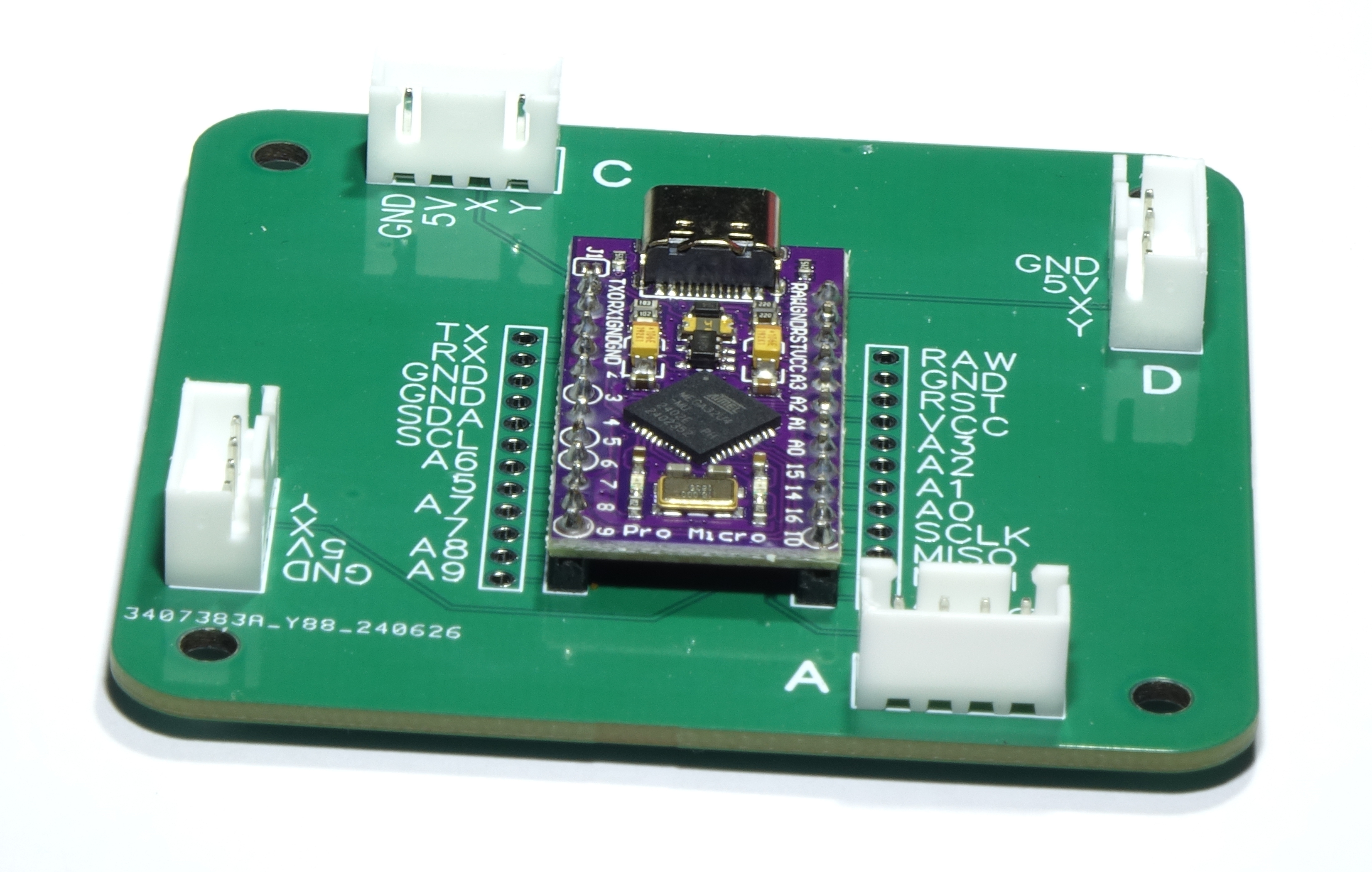
Trim the wires on the JST XH connector to length.
(Note that the pictures are a bit out of sequence - but you get the idea 😁)
For the neatest result, these wires need to be trimmed in a staggered fashion. Wire Cutting Gauge.stl allows you to cut them to an optimal length.
Note the orientation of the plug - the GND wire (the red wire in this case - you will get many wire colour variations) must be the longest wire.

Strip 4mm of insulation

Solder them to the joystick PCB as shown
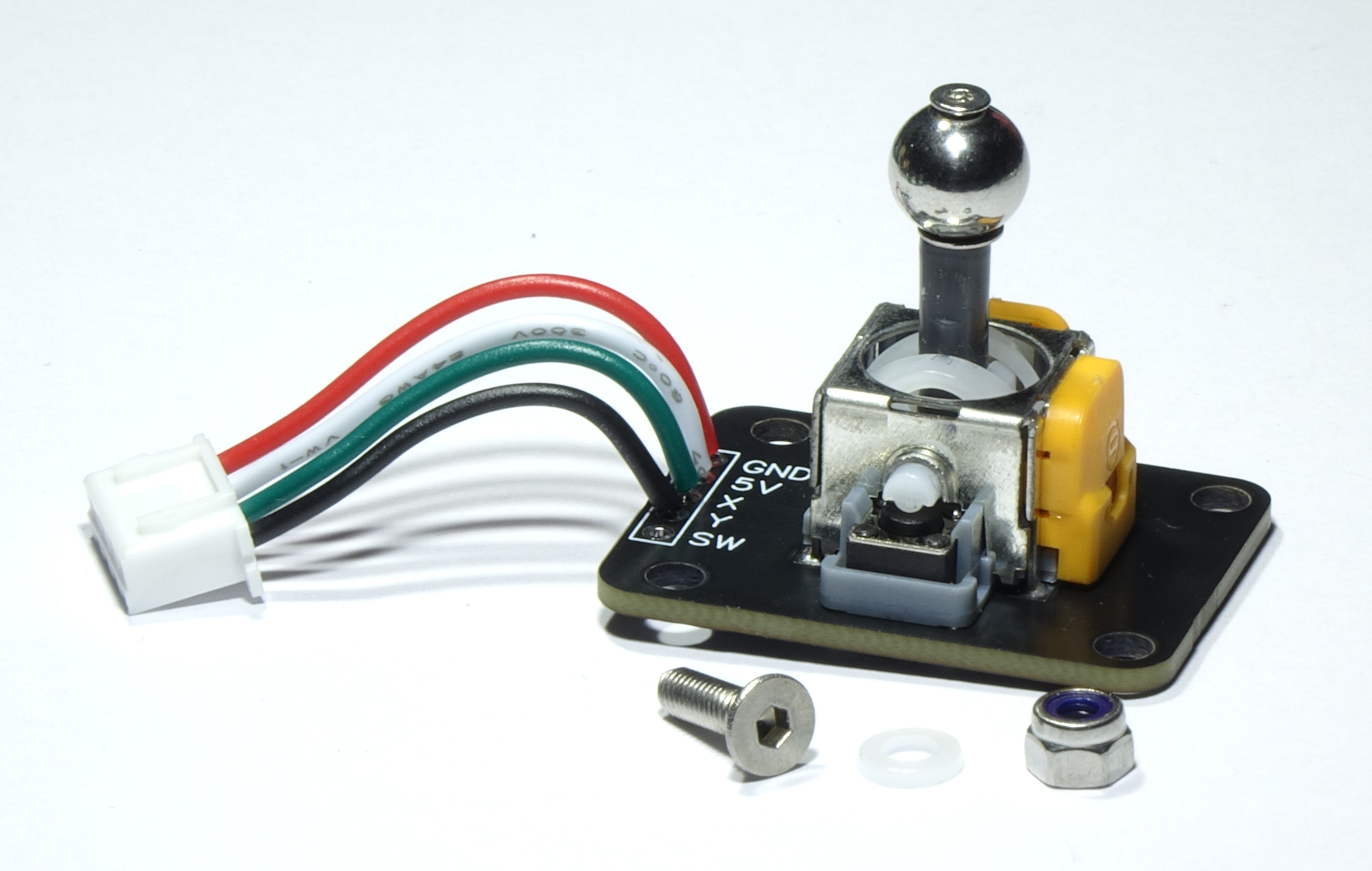
Attach to the joystick frame with 10mm M3 countersunk screws, M3 nuts ("nyloc") and use a nylon or fibre washer to protect the PCB.

Thread the middles of the 608 bearings over the joysticks and clamp the top and bottom domes in place over them using 10mm M2.6 self tapping screws.
Attach the lid using 10mm M2.6 self tapping screws.
Attach the knob using a 10mm M3 self tapping screw.
Plug the USB cable into the Arduino and attach the PCB to the joysticks (there is just enough room - some long nosed pliers may help to hold the plugs).
Secure the base with 10mm M3 countersunk self tapping screws.
Current firmware (thanks Andun_HH@Andun_HH).
https://github.com/AndunHH/spacemouse
Calibration/Tuning
The combination of the Hall effect joysticks, ball bearing mechanical action and reduced size/geometry has resulted in very smooth operation. There are plenty of opportunities for more fine tuning, but it works very well as it is (if I say so myself 😀)
After the initial calibration stages as documented in the firmware I found the following settings to be a good starting point
#define MODFUNC 3
#define DEADZONE 20
#define TRANSX_SENSITIVITY 3
#define TRANSY_SENSITIVITY 3
#define POS_TRANSZ_SENSITIVITY 5
#define NEG_TRANSZ_SENSITIVITY 5 //I want low sensitiviy for down, therefore a high value.
#define GATE_NEG_TRANSZ 15 // gate value, which negative z movements will be ignored (like an additional deadzone for -z).
#define GATE_ROTX 15 // Value under which rotX values will be forced to zero
#define GATE_ROTY 15 // Value under which roty values will be forced to zero
#define GATE_ROTZ 15 // Value under which rotz values will be forced to zero
#define ROTX_SENSITIVITY 1.5
#define ROTY_SENSITIVITY 1.5
#define ROTZ_SENSITIVITY 2