
Arduino Scantable
Obliczymy ostateczną cenę na podstawie wybranego pliku. Sprawdzisz ją i zaakceptujesz przed płatnością.
Zapisane na tym urządzeniu.
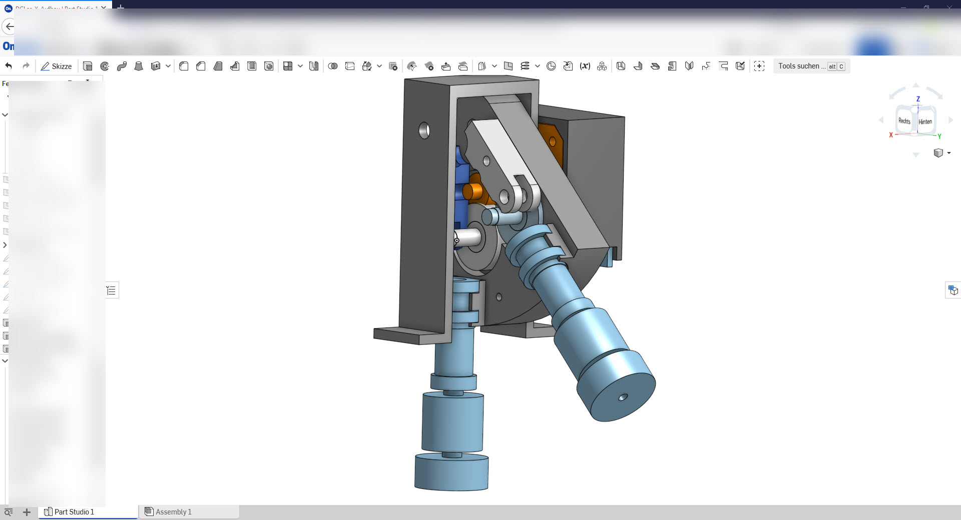
Scantable Arduino for Scanner Scan-Drehteller mit Arduino Stepper-Kontrolle für Scanner
- Ocena
- 0 / 5
- Polubienia
- 3
- Pobrania
- 34
- Wydruki
- 0
- Wyświetlenia
- 365
- Oceny
- 0
Aktualizacja u źródła:
Informacje o modelu
- Źródło
- Printables
- Kategoria
- Other Gadgets
- Licencja
- Creative Commons — Attribution — Noncommercial
Hallo,
ich habe schon lange mir Optimierungen für den Scan bei Vorlagen für den 3D Druck überlegt. Als ich dieses “Holow Clock” Projekt sah und mir nachbaute, dachte ich mir, daß ist doch eigentlich eine gute Basis für das Thema Scanner. Das "Lastenheft" war, dank der Aduino-Sketch-Datei und den Anleitungen zum Verkabeln recht schnell zusammen gestellt. Das Teil greift auf die gleichen Elektro-Bauteile zu. Silikonfett braucht es keines, da ich kein Getriebe verwende. Allerdings verwende ich 3 Lager, die den Drehteller außen “abstützt”. Diese haben 17 mm außendurchmessr 6 mm Wellendurchmesser und 7 mm Breite - Bezeichnung z.b. 606. Der Drehteller ist in Schwarz gehalten, was beim Scannen von Vorteil ist. Es gibt so nette Gadgets, die den Scanner unterstützen. Sind kleine Klebeicons, die dem Scanner helfen, sich im “Raum” zu orientieren. Ich dachte mir, es wäre vielleicht günstiger und hilfreicher, diese gleich in den Drehteller zu integrieren. Dabei habe ich dann auch gleich noch das Zentrum des Tellers “markiert”. Diese Symbole und der Zentrummarker sind in Staubgrau von M4P gedruckt - eine ekelhafte Farbe zum drucken, aber Kameras und Scanner “lieben” sie, weil Sie max. Kontrast ermöglicht…! Ich verlinke hier einfach mal den Ursprung, weil dort auch auf die Verkabelung und das aufspielen des Sketches auf den Arduino erläutert wird…
Das Update vom 23.12.2024 hat die Umstellung von 608er auf 606er Lager erfahren, wobei ich auch alternativ Druckbare Gleitlager jetzt beigefügt habe. Ebenso kann nun auch die Abdeckung und der Boden miteinander verschraubt werden. Dazu bedarf es 2 M3er Ruthex-Muttern und 2 Schrauben M3 10 mm bzw. M3 15 mm, je nachdem, was so greifbar ist… ;-)
Gleichzeitig habe ich nun alle Dateien auch als Step-Dateien eingefügt.
Hello,
I've been thinking about optimizing the scanning of templates for 3D printing for a long time. When I saw this “Holow Clock” project and built it, I thought to myself that this is actually a good basis for the topic of scanners. Thanks to the Aduino sketch file and the wiring instructions, the “specifications” were put together quite quickly. The part uses the same electrical components. It doesn't need silicone grease as I don't use a gearbox. However, I use 3 bearings that “support” the turntable on the outside. These have an outer diameter of 17 mm, a shaft diameter of 6 mm and a width of 6 mm - designation e.g. 606. The turntable is black, which is an advantage when scanning. There are some nice gadgets that support the scanner. These are small adhesive icons that help the scanner to orient itself in “space”. I thought it might be cheaper and more helpful to integrate them into the turntable. I also “marked” the center of the plate at the same time. These symbols and the center marker are printed in dust grey from M4P - a disgusting color for printing, but cameras and scanners “love” it because it allows maximum contrast...! I'll just link to the source (sorry, German movie) here, because it also explains the wiring and how to transfer the sketch to the Arduino…
The update of 23.12.2024 has seen the changeover from 608 to 606 bearings, whereby I have now also included alternative pressureable plain bearings. The cover and base can now also be screwed together. This requires 2 M3 Ruthex nuts and 2 M3 10 mm or M3 15 mm screws, depending on what is available... ;-)
At the same time, I have now added all the files as step files.