
wind turbine
Obliczymy ostateczną cenę na podstawie wybranego pliku. Sprawdzisz ją i zaakceptujesz przed płatnością.
Zapisane na tym urządzeniu.

working wind turbine model with room to insert small generator
- Ocena
- 5 / 5
- Polubienia
- 170
- Pobrania
- 736
- Wydruki
- 2
- Wyświetlenia
- 5457
- Oceny
- 2
Aktualizacja u źródła:
Informacje o modelu
- Źródło
- Printables
- Kategoria
- Other Ideas
- Licencja
- Creative Commons — Attribution — Noncommercial
Introduction
This model of a wind turbine is fully functional and turns even when there is little wind, as can be seen in the following video.
The model has a modular design and consists of three assemblies: the rotor, the housing and the tower.
To ensure printability, the assemblies themselves have been broken down into individual parts. These must either be glued together or connected with screws. Magnets are used to facilitate the removal of the housing cover, as can be seen in the following video.
Required hardware:
- M8 threaded rod (100 mm)
- M8 nuts (4x)
- M8 screws (M8x20) (4x)
- Ball bearing (608ZZ) (2x)
- magnets 10x2 mm (4x)
(Variant without magnets, but not tested)
Printing
In this section, I would like to give you a few tips on the print settings.
Let's start with the positioning of the models on the print bed:
Rotor
The rotor hub is printed horizontally. Organic support structure is used for this.

The rotor blades should ideally be printed upright, as shown. The use of Brim is recommended here.

The connectors are also printed upright.
Housing
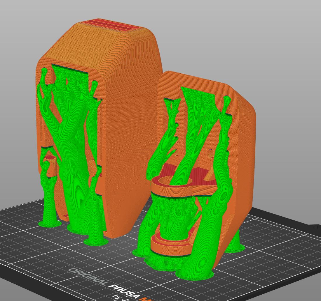
The housing is also best printed upright. This allows the curves to be printed well. However, support material must be used here. I recommend the organic support material.

Tower
The tower is also printed upright. Only a little support structure is needed here. I recommend snug.

Assembly
The support structure is removed first and then the individual assemblies are put together:
Rotor blades
The individual segments are aligned with the connectors and then glued together with adhesive (e.g. superglue).
After curing, the rotor blades can be attached to the hub. Glue may also need to be used here.
Housing
Remove support
10x2 mm magnets are used for the housing with magnets. These are glued into the positions shown. The ball bearings are then inserted.


Tower
The screws are inserted first and then the cover is glued in place. This is simulated in the video.

Final assembly
The tower segments can now be bolted together. It may be necessary to use a thread cutter for this.
The threaded rod is then cut to length and screwed into the hub.
The threaded rod can now be fitted with nuts and guided through the ball bearings. It is then fixed in place with nuts.
It is now possible to attach a small generator to the threaded rod to operate a small lamp.
Closing remark
I hope you enjoy the model as much as I do.
I would be very happy about a Like and please give feedback or upload a make.