
Modular tool for teaching physics
We calculate the final price from your selected file. You review and accept it before payment.
Saved on this device.
Model information
- Source
- Printables
- Category
- Physics & Astronomy
- License
- Creative Commons — Public Domain
Thit text is google tranlate for my article about this set.
Production
The Prusa Mini+3D printer was used to produce individual parts. The following conditions were determined for production.
• Possibility to use 4,5V battery.
• Printing on a 3D printer with a printing volume of 180 × 180 × 180 mm.
• Minimum number of parts bought. (Steel bars, electric motor, switch,…)
• Combining parts by friction.
• Mirror use of parts.
• Possibility to measure multiple types of meters.
Some parts were required higher strength. Here it was necessary to use the screws. It was necessary to choose the appropriate dimensions to find use in other modules for the selected screws. M3 screws were selected. For these screws, additional uses were found such as wheel axes and electrical contacts.
Individual parts of the set
The following part is devoted to the description of individual parts and modules.
Wheelchair
The track consists of two hammered steel bars with a radius of 8 mm and a length of 1000 mm set with friction in printed legs. In the legs you can see rectangular holes with dimensions of 60 × 15 × 20 mm, which are used to attach modules for meters and pulleys.
The trolley is secured with the third pair of wheels. The third pair of wheels is attached by means of screws so that the truck can be removed from the track without the need to dismantle. The trolley moves on the track-only in one axis. In the trolley there is a hole with a size of 100 × 65 × 30 mm for the modules of uniform attempts. To reduce friction, the axes of the wheels are lubricated.
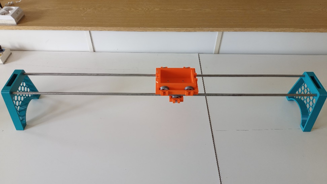
Figure 1: A wheelchair track.
Flettner's rotor
It is a demonstration experiment of the Magnus phenomenon, when the rotating body of the volatile body, which puts the body in motion. The demonstration of the experiment is done by turning the electric motor on the switch and the cylinder spins. When blowing with a vacuum cleaner or hairdryer, it is moving to move in the direction where pressure is reduced due to the magnus phenomenon. [4]
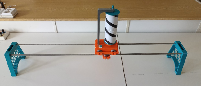
Figure 2: Flettner Rotor module fastened in a wheelchair.
This is the most complex module that contains a 4.5 V battery, an electric motor and a switch. A paper roll was chosen for the cylinder (to simplify the production process). The stripes serve as visual evidence of rotation. The cylinder rotation direction can be changed by changing the polarity by turning the battery. The module has a covered opening for the future assembly of the commutator.
The experiment can also be complemented using another module that simulates the aircraft wing.
Uniform acceleration
From the second Newton law, the resulting force is needed to accelerate. If we want to demonstrate the law in the classroom is difficult to maintain this power. This problem is solved by the subsequent module. It is a pulley where a trolley is placed at one end of the rope and on a dirty weight. When the weights are released, the truck begins to accelerate.
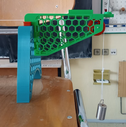
Figure 3: Module for fastening the tirorer with pulley and weight.
On the other side of the track is the same pulley on which the ultrasonic distance meter is attached. Movement can also be measured using a video. It is very easy to change the parameters by simple adding weights to the hinge or to the wheelchair.

Figure 4: Look from the side of the assembly for evenly accelerated movement.
Tilted plane
For the assembled track, one side can be supported to obtain a tilted plane. On it we can examine the decomposition of forces, and then accelerate on the inclined plane. The necessary measurements can be performed using both digital and analog tirometer.
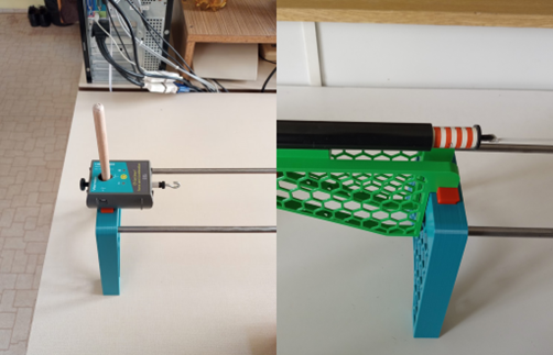
Figure 5: Fastened tir meters, vernier tir meter on the right, spring tirter on the left.
Two hanging modules were made for tilt measurement. The first is a tilt lead meter and the second mobile phone holder on which Protractor is running. Both modules are suspended using neodymium magnets.
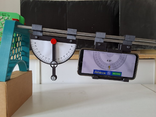
Figure 6: Measurement of tilt using a lead meter and phone.
By wrapping a body with a real liquid
When examining air resistance, an experiment is often used with a hanging ladle, when it blows in a stupid, hollow, hollow, and finally flat part (hollow by cardboard). The resistance is determined according to the resulting tilt. [5]
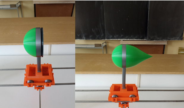
Figure 7: Defustible drop module.
For this module, all previously mentioned measurements can be made and obtained by specific numeric values. The whole module is based on the shape of the drop and the individual parts are connected by means of a thread. Individual parts can be changed to adjust the necessary shape. There is also a set of weights to replenish the weight after removing parts of the drop and maintaining the total weight of the module.
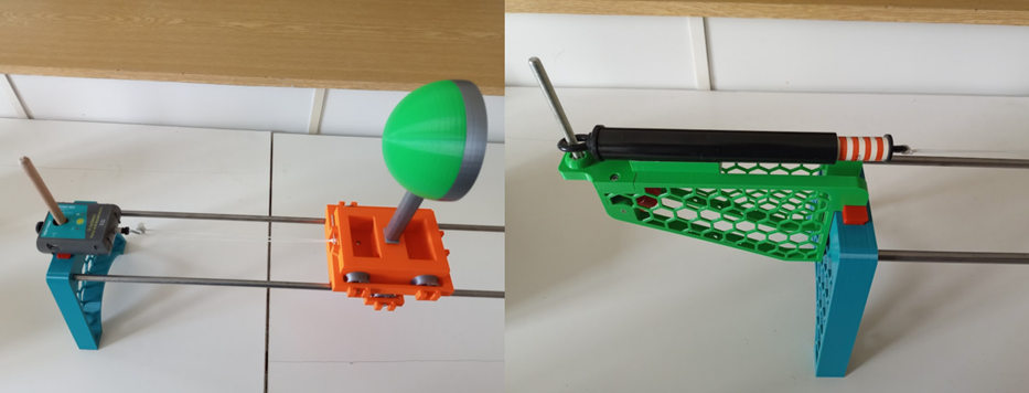
Figure 8: Measurement options using tirometers.
Measurements can be performed using both digital and analog tirliometers.
Universal module
The last module is a prism with holes attached to the wheelchair. The module also serves as support for further experiments.
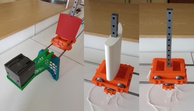
Figure 9: Use of the universal module.
Figure 9 shows use with other components of the set. With the red plate it serves as a reflective plate for an ultrasonic distance meter. And the red plate itself serves, the same as the white wing of the plane, for evidence of the Magnus phenomenon, as it is convex on the other side.
The module itself is intended as a mast for sail models and subsequent exploration of their effect.