
FT EMS Voron 2.4 350mm (LDO Laser Cut)
We calculate the final price from your selected file. You review and accept it before payment.
Saved on this device.

This is the LDO exclusive FT EMS V2.4 350mm laser cut single piece frame
- Rating
- 5 / 5
- Likes
- 18
- Downloads
- 90
- Makes
- 2
- Views
- 1,762
- Reviews
- 1
Updated at source:
Model information
- Source
- Printables
- Category
- Voron Parts & Upgrades
- License
- Creative Commons — Attribution — NoDerivatives
INTRODUCTION
Not a fan of DIN rails and VHB tape - Sorry Voron Design team. You are in the right place when it comes to Electronics Management Systems aka FT EMS. This is our single piece acrylic laser cut FT EMS frame that fits onto the Voron V2.4 350mm build.
THE DESIGN
The design was refined from the publicly available printable version of the FT EMS frame. Ideally, FT EMS V2.4 350 laser cut should be installed when initially building the printer. It can also be used to upgrade an existing printer but it does mean removing all the electronics and the bed from the printer. You will need to print the mounts and cable ducts that match the electronic components you are using which can be done on a smaller print bed.
The components are designed and mounted on hex stand-offs and can be moved to wherever your heart desires. My initial implementation is intended as an example but it really is up to the end user to place the parts where they want them to be located and print only what is needed.
BOM
- FT EMS Voron 2.4 350 build frame
- Smoked Deck Panel for Voron V2.4 350mm build
- 14 x M5 T-Nuts
- 14 x M5x10 BHCS
- 28 x M3 Threaded Inserts
- 28 x M3x6 BHCS

INSTALLATION INSTRUCTIONS
EMS is designed to be extremely flexible as to let the user decide what hardware to use on the printer. Therefore we have created a mounts repository where power supply, controller board, expansion board and single board computers (Raspberry Pi) mounts are stored. Please visit our mounts repository to download universal cable ducts and mounts for the hardware you intend to install - https://www.printables.com/model/558357-ft-ems-mounts-repository
We recommend printing the whole set of parts and test fit them outside of the printer prior to installation. This will serve as a double check to ensure that all the correct parts are printed and prepared.
- Install the M3 threaded heat inserts into [a]_frame_mount_top_x12 and [a]_base_mount_top_x2
- Attach [a]_frame_mount_top_x12 and [a]_fram_mount_bottom_x12 to the 12 locations around the EMS frame using 24 x M3x8 SHCS screws
- Attach [a]_base_mount_top_x2 and [a]_base_mount_bottom_x2 to the 2 locations on the EMS frame using 4 x M3x8 SHCS screws

Think of EMS as Lego. You can literally mount any combination of hardware using our extensive mounts located in our mounts repository. Below is a sample of how the electronics components can be organised making the build clean. This sample uses the following parts: -
- Mean Well LRS-200-24 Power Supply
- Mean Well RS-25-5 Power Supply (optional if you need additional 5V power)
- LDO Voron Leviathan V1.2
- Omron G3NA-210B-1 SSR
- Raspberry Pi 4 Model B
Which hex mounts do I need? Here is a breakdown of what each are used for: -
- Mount A = hole directly in the center of the hex and the screw is inserted from the mount side
- Mount B = hole is with a 5mm offset and the screw is inserted from the mount side. Depending on which direction you need the offset you can rotate the hex so its actually 5mm offset in 6 directions!
- Mount C = Cable tie in the center of the hex in the vertical orientation
- Mount D = Cable tie in the center of the hex in the horizontal orientation
- Mount E = These are used for electronic mounts that have a heat insert in them. The screw will go through the center of the hex from behind into the mount. These are typically used for SSR and some PSU mounts.
- Mount F = These are used for electronic mounts that have a heat insert in them. The screw will go through the center of the hex from behind into the mount. These are typically used for SSR and some PSU mounts.
- EMS Bolt = this is used for awkward mounts and load into the channel on the electronics mount with an M3 heat thread insert preloaded. These work in combination of Mount E and F.

It is highly recommended to mount all of the electronics while the frame is outside of the printer to confirm the location of parts. Most electronic boards can be removed and re-attached once the printer is installed as the screws are inserted from above the boards. The exception would be the power supplies which will need careful adjustments to have them mounted so they are recommended to be preinstalled before the EMS frame is mounted to the printer.
- Preload 12 x M5 T-Nuts into the 4 bottom extrusions of the frame
- Bring the frame into place and ensure all M5 T-Nuts are aligned - the picture below is to show how things connect but the frame must be installed flush with the frame
- Attach FT EMS frame to the frame using 3 x M5x10 BHCS screws per side
- Repeat for the other 3 sides

- Place the replacement smoked deck panel (optional) before installing the 2 x bed extrusions.

- Preload and align 2 x M5 T-Nuts into the bed extrusions (1 T-Nut into each) facing down towards the EMS frame
- Secure the EMS frame into the bed extrusions using 2 x M5x10 BHCS screws
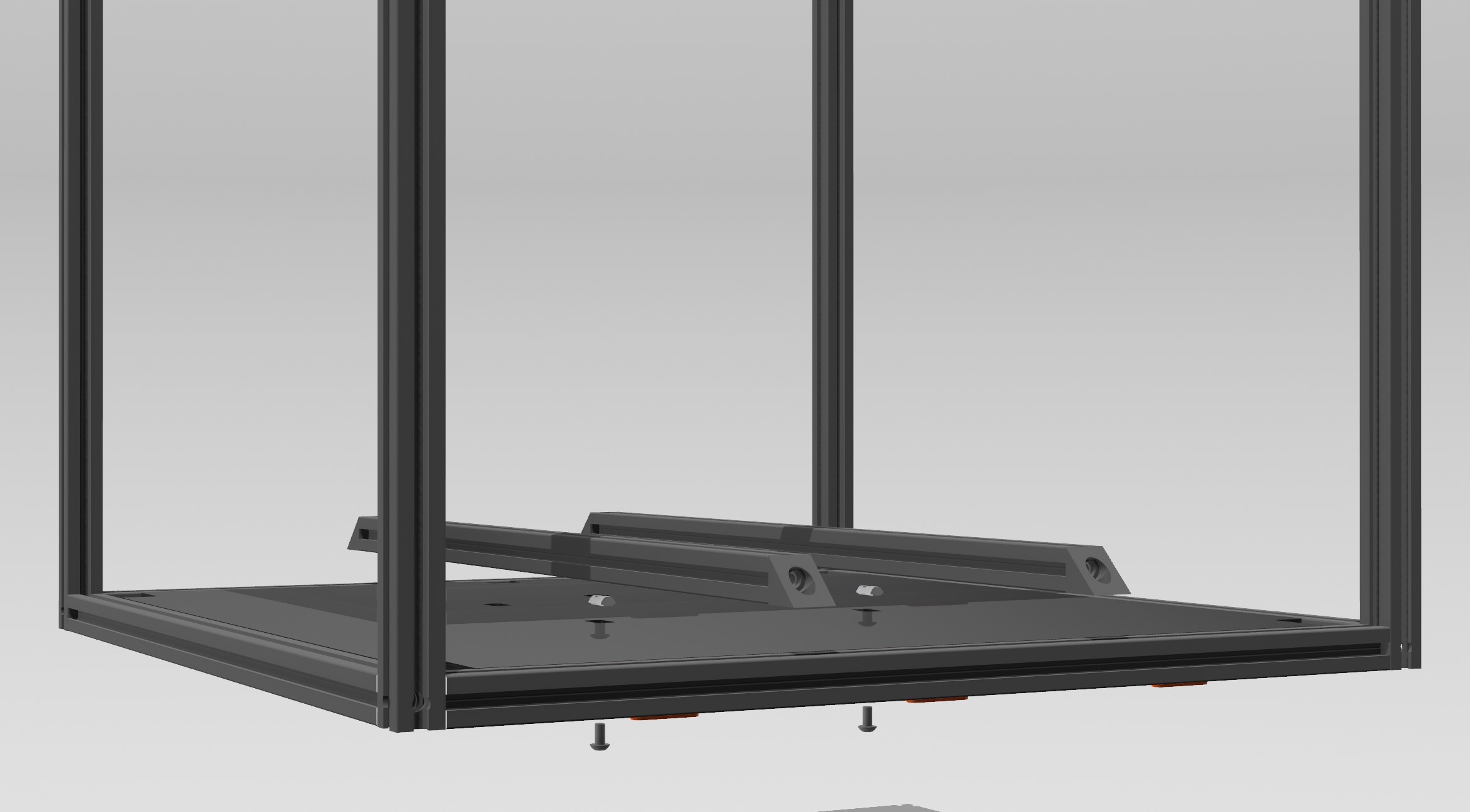
- Secure the 2 x bed extrusions to the frame using 4 x M5 1mm shim and SH4 x M5x10 BHCS screws as per the Voron manual
Should you have any questions you can reach out to us via Discord