
Tesseract prop (interactive)
We calculate the final price from your selected file. You review and accept it before payment.
Saved on this device.

A real-life sized tesseract with lighting effects
- Rating
- 5 / 5
- Likes
- 6
- Downloads
- 87
- Makes
- 1
- Views
- 585
- Reviews
- 1
Updated at source:
Model information
- Source
- Printables
- Category
- Props
- License
- Creative Commons — Attribution — Noncommercial — NoDerivatives
This guide will help you build a movie-size accurate Tesseract prop with interactive lighting effects, perfect for display or cosplay. Follow these steps closely to ensure proper assembly.
Note:
This prop is for personal use only.
NO COMMERCIAL USE ALLOWED without prior authorization. This includes usage in ad-supported media.
If used in cosplay photos or videos, please credit this page for attribution.
Material necessary:
- 3-part print, in Fillamentum Crystal Clear Blue or similar translucent filament
- Print the baseplate stem side up
- Print the body upside down
- Print the sphere laying on the cuts
- 4 M3 brass inserts and 4 M3x10 countersunk head screws.
- 1 ESP32, D1 mini, or equivalent microcontroller (get the version without pre-soldered Dupont pins).
- 2 meters of 26AWG ribbon cable.
- 17 WS2812B PCB-mounted individual 5050SMD led diodes. Buy a few spares, if you are not used to them it's easy to mess up soldering.
- 1 MPU-6050 accelerometer
- One modular USB plug plus two thin, possibly transparent, AWG20 wires, 1.5 meters long. Commonly found as part for lighting equipment.

Tools:
- Soldering iron and solder. Strongly suggest a TS101 or similar, to fit the small spaces.
- Small pliers.
- Electrician's scissors.
- Hot glue gun.
- Screwdriver.
Step-by-Step Instructions:
- Print the Components
- Print the 3-parts of the Tesseract using 100% concentric infill, 0.08 mm layer height, and no brim (except for the LightCap if needed).
- Speed: Slow the print speed to 120 mm/s or less for PLA to avoid defects.
(Note: The main body may take up to 24 hours to print.)
- Prepare the Microcontroller
- Connect the microcontroller (ESP32, D1 mini, or similar) to your PC via USB.
- Load the program attached into the Arduino IDE.
- If it doesn't show up by itself, remember to create a separate tab named HueFix.h and import the content of the file of the same name.
- Look online for the PINOUT DIAGRAM of your microcontroller. Look for a suitable pin to be used as data line
- For ESP32 use pin 14
- For D1 Mini use pin 6
- Change the lighting pin to your preferred data pin at line #18.
- Upload the program using Arduino IDE, following the instructions specific to your microcontroller. You may be prompted to install some libraries, in case do so from the Library Manager (CTRL+SHIFT+I).
- Prepare the Power Wires
- Assemble two power wires to the USB plug, using the VCC and GND pins (ignore data pins).
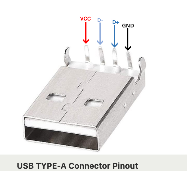
- Run these wires through the hole at the bottom of the light stem and base of the pillar. The USB connector shall be towards the flat side of the base.
- In alternative, you could use a pre-made USB cable, but it will be more visible. Just find the VCC and GND wires with a multimeter, and cut the other two.
- Assemble two power wires to the USB plug, using the VCC and GND pins (ignore data pins).
- Power Lines and Soldering
- Find the VCC and GND pins on your microcontroller using the pinout diagram.
- Cut four 15 cm strands from the ribbon cable, ideally 2 red and 2 black,
- Connect them to the power wires on one side. Solder two of them to the positive cable (RED) and two to the negative cable (BLACK).
- You have now two strands of three wires, one positive and one negative. Solder the red wires to the VCC of the microcontroller, and the black wires to the GND.
- Run one power line (red+black) up into the stem, leaving loose wires in the "ball" area for the LEDs.
- Connect the MPU-6050 Accelerometer
- Solder one power line (the one not leading to the “ball”) to the MPU-6050, connecting VCC to VCC and GND to GND.
- Run two wires from the SCL and SDA pins of the microcontroller to the MPU-6050, soldering them to the corresponding pins. Check the SCL and SDA pins for your controller on the pinout diagram
- for ESP32: SCL #22, SDA #21
- for D1 Mini: SCL #D1, SDA #D2
- Ignore the other pins on the accelerometer
- LED and Data Line Setup
- Solder one length of colored wire to a the data pin you chose before on the microcontroller (e.g., Pin 14 on ESP32, Pin 6 on D1 Mini). Run this data line up into the stem along with the power lines for the LEDs.
- Trim the wires to allow just enough length for soldering.
- Solder the data line to the “DI” pad on the first LED.
- Solder the power lines to the VCC (+5V) and GND (-) pads next to the “DI” pad.
- Continue soldering 3 cm wire patches from the “DO” pad of each LED to the “DI” pad of the next, creating a chain of LEDs spaced 3-4 cm apart.
- Testing
- Connect the microcontroller to a USB power bank for testing.
- If there’s no light or you see the magic smoke escaping, you may have shorted a connection. Double-check your work and replace any damaged components as needed. Don't worry too much, it happens.
- If everything works, wait for the self-check (colored dots), until the lights flash white. It should take roughly 6 seconds.
- Final Assembly
- Glue the LEDs into the holes of the light stem and cap. Ensure the LEDs are firmly secured in place.
- Glue the cap on top to form a “ball” of LEDs.
- Mount the microcontroller and accelerometer to the inside of the baseplate. Ensure the accelerometer is flat and securely in place.
- Install the baseplate on the body of the Tesseract and secure with 4 screws.
- Powering Up
- Connect the USB power bank to the Tesseract.
- IMPORTANT: Lay the Tesseract flat for 5-8 seconds when powering it up. This allows the accelerometer to self-calibrate. Once it flashes white, it's ready.
- Notice: you can disable the colored self-check in the program by editing out lines 42-45
Features:
- Impact response: The light flashes brighter with a tap or hit.
- Movement response: The cloud effect speeds up when the Tesseract is moved.
The Tesseract will run for around 15-20 hours on a 10,000mAh USB power bank, with the power cable hidden in your sleeve.
Note:
This prop is for personal use only.
NO COMMERCIAL USE ALLOWED without prior authorization. This includes usage in ad-supported media.
If used in cosplay photos or videos, please credit this page for attribution.