
Prusa Mini+ Stacklight
We calculate the final price from your selected file. You review and accept it before payment.
Preliminary estimate for PETG
€7.46 – €9.12 net (excluding VAT)
For file: 20241020_Stacklight Mount_PETG_0.4n_0.2mm.bgcode
This is an estimate for one file. You’ll confirm the exact price before ordering.
File and estimate settings
File used for this estimate
Average indicative estimate: €8.29 excluding VAT (range midpoint).
- Weight reported by the author
- 154 g
- Print time reported by the author
- 6.38 hr
- Source material
- PET
- Estimate material
- PETG
- Estimate printer
- Bambu Lab P1S - 0.4 nozzle
- Estimate process
- 0.20mm Standard
Indicative estimate for the selected file only, based on the author’s weight and print time. File variants are not added together. The final price is calculated after file analysis.
Saved on this device.

A stacklight for the Prusa Mini+ 3D-Printer, to indicate printer status.
- Rating
- 0 / 5
- Likes
- 11
- Downloads
- 23
- Makes
- 0
- Views
- 427
- Reviews
- 0
Updated at source:
Model information
- Source
- Printables
- Category
- Prusa Parts & Upgrades
- License
- Creative Commons — Attribution — Share Alike
About
In the industry, most machines have a stacklight so machine status is easily visible from afar. Let's do the same with a 3D-printer: This is a stacklight for the Prusa Mini+. It should be possible to adapt this to other 3D-printers.
Accompanying this project, I have also written a blog post with a bit more details about stack light usage in the industry: Stack Lights — blog.rahix.de
Details
The stacklight connects to the printer via the I2C bus on its expansion header (J23). A small PCB is needed which houses an I2C port expander and some relays for the 24V stacklight signals. All design files are included.
To control the stack light, M260 G-Codes are inserted into the print files which set the appropriate stacklight colors (needs firmware ≥6.1.2). This has the advantage that no firmware modification is needed. However, there are some limitations: The stack light cannot be updated in certain abnormal situations as shown below.
| Situation | Stack Light Signal | Recommended Color |
|---|---|---|
| Power On/After Power Interruption | FAULT | ORANGE |
| Print Started/Running | OPERATE | WHITE |
| Print Completed/Ready to remove | READY | BLUE |
| Print Paused on Color Change | READY | |
| Print Paused on Slicer Pause | READY | |
| Print Aborted | not possible via G-Code | |
| Print Paused Manually | not possible via G-Code |
Additional Parts
In addition to the printed parts, you will need:
| Amount | Part | Link |
|---|---|---|
| 2x | M5x8 countersunk screw (e.g. DIN 7991/ISO 10642) | |
| 2x | Slot nut/Hammer nut for 8mm slots (alternatively, you can print one) | |
| 4x | M3x8 cylinderhead screw (e.g. DIN 912/ISO 4762) | |
| 2x | M3x8 countersunk screw (e.g. DIN 7991/ISO 10642) | |
| 6x | M3 L5.7 threaded inserts | CNC Kitchen |
| 4x | M5x16 cylinderhead screw (e.g. DIN 912/ISO 4762) | |
| 4x | M5 nuts (e.g. ISO 4032) | |
| 1x | Molex 0513821000 Connector Housing (for the J23 expansion connector) | DigiKey |
| 10x | Molex 0561349100 Crimp Socket (for the J23 expansion connector) | DigiKey |
| 1x | Automotive Add-On Circuit (for stealing the 24V DC from the heater fuse) | Details on the Prusa Forum |
| 1x | Dupont Pin (either bare or pre-crimped to a wire, ideally with a cross-section ≥0.34mm²) | |
| 1x | Stacklight Controller PCB (check the included design files) | |
| 1x | 3-color stacklight 24V DC, NPN |
Recommended Printing Parameters
| Orientation | Print in the provided orientation of the STL file |
|---|---|
| Support Material | Print without support material |
| Layer Height | 0.2 mm |
| Nozzle Diameter | 0.4 mm |
| Material | PETG |
Build Instructions
1 - Stacklight Controller PCB
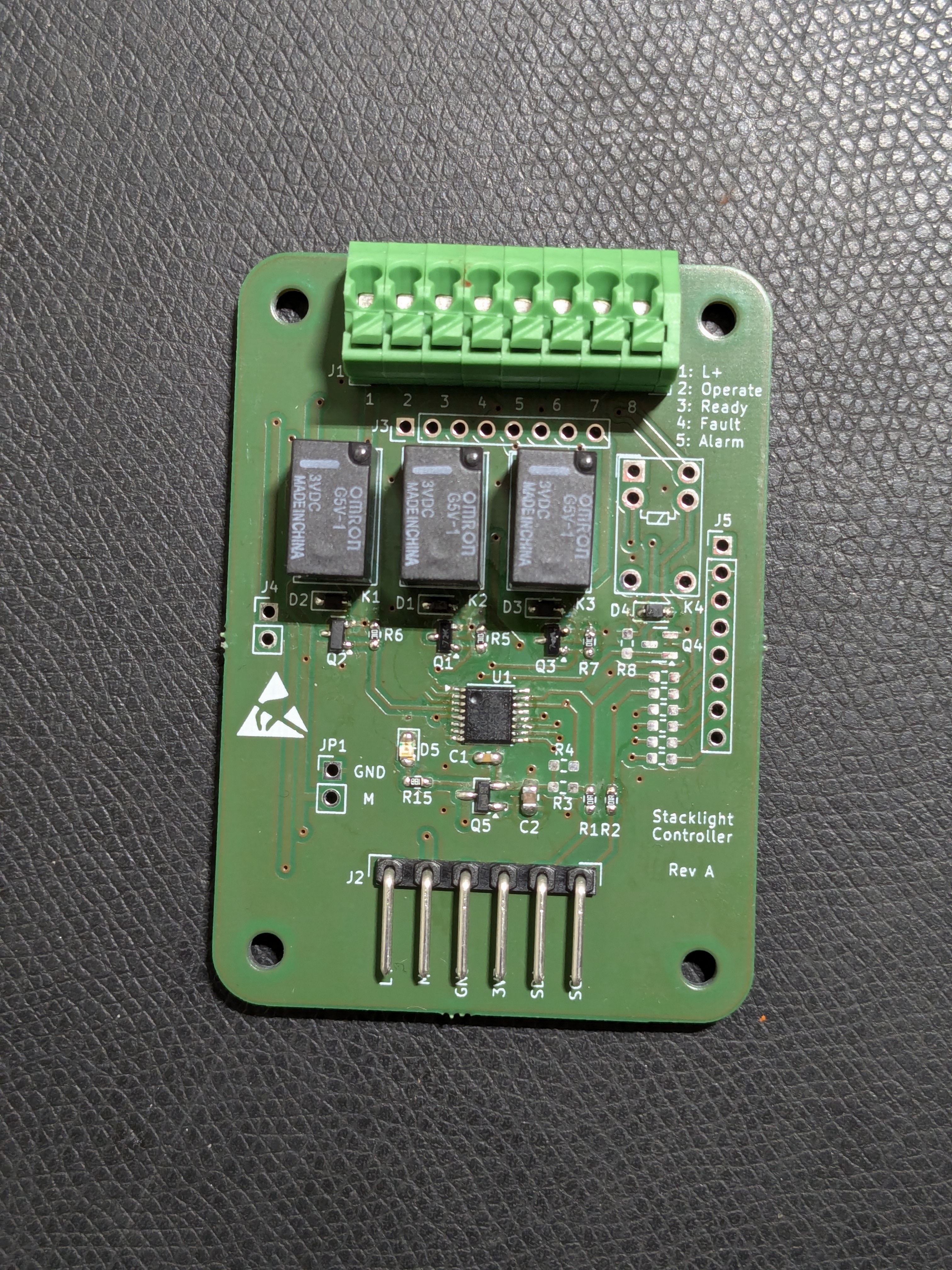
- Check the included KiCAD project archive for the PCB and BOM. There is also an iBOM (HTML) for easy assembly.
- Don't be confused by the empty footprints on the right — these can be used for one more controllable 24V output, but are not needed for the standard stack light usage.
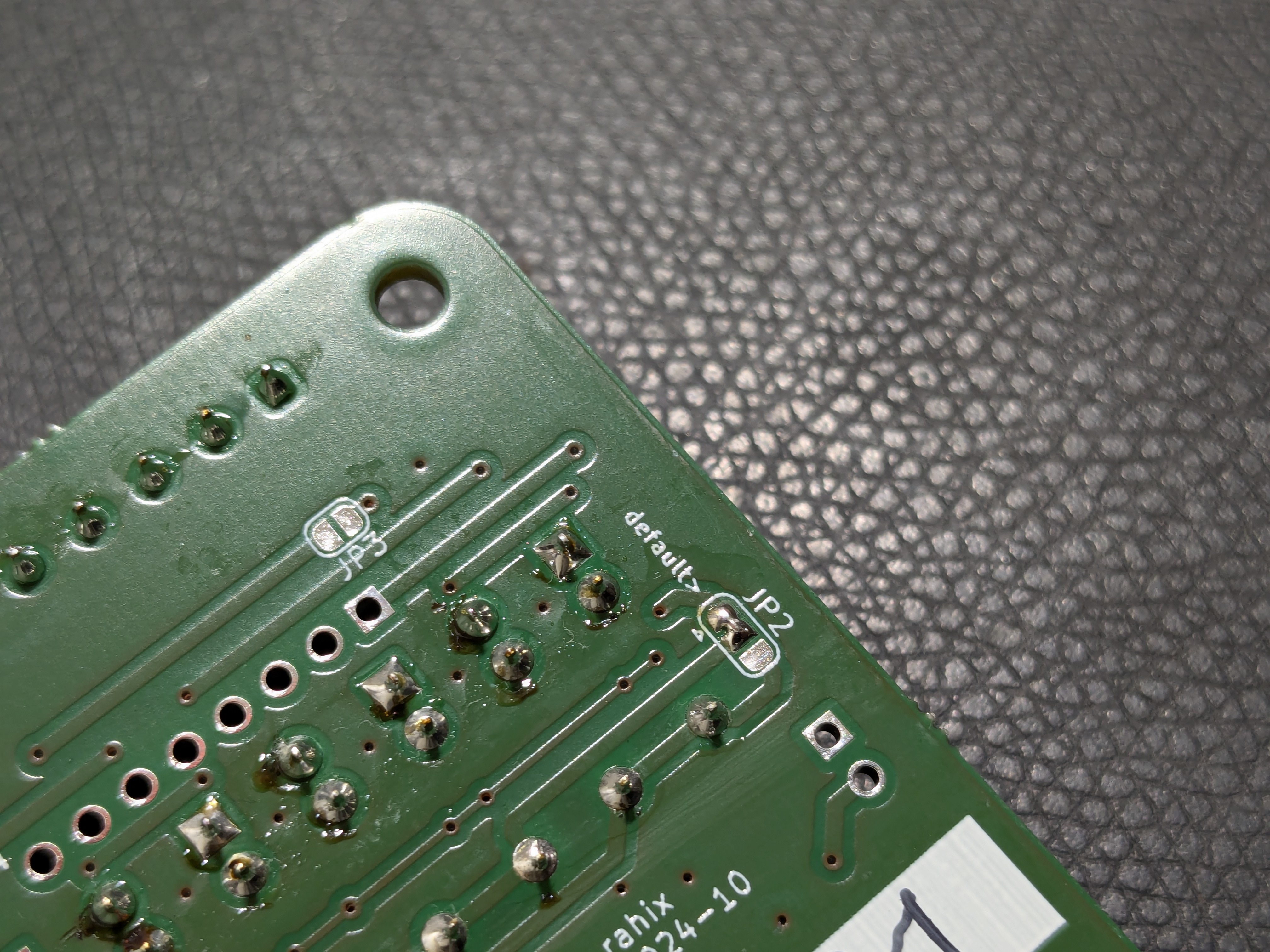
- Make sure to close the three-way jumper on the back into the direction that's marked “default”.
2 - Installation
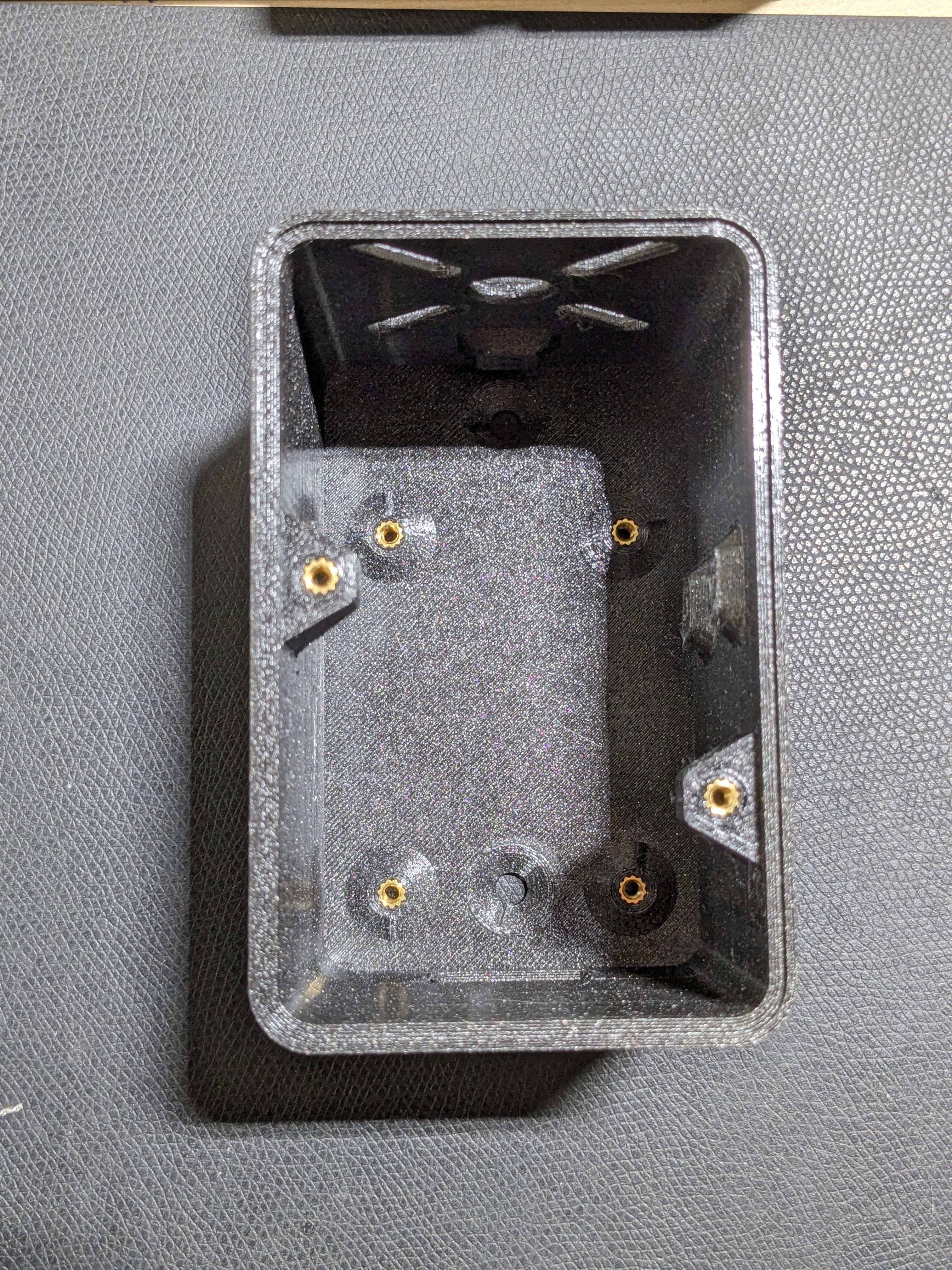
- Install 6 M3 threaded inserts into the printed enclosure. 4 into the standoffs where the PCB is mounted and 2 into the appropriate holes for the lid.
- Install the enclosure to the side of the Prusa Mini+ using 2x hammer nuts and 2x M5x8 countersunk screws.
- Install the stacklight controller PCB into the enclosure with 4x M3x8 cylinderhead screws.
- Attach the stacklight to the mounting hole pattern on the top, with 4x M5x16 screws and nuts. The wires from the stacklight should enter the enclosure through the center hole.
3 - Wiring Harness
- Terminate the stacklight wires to the top connector of the PCB (J1) as detailed in the wiring diagram. You can use the ziptie mounts in the enclosure for wire management.
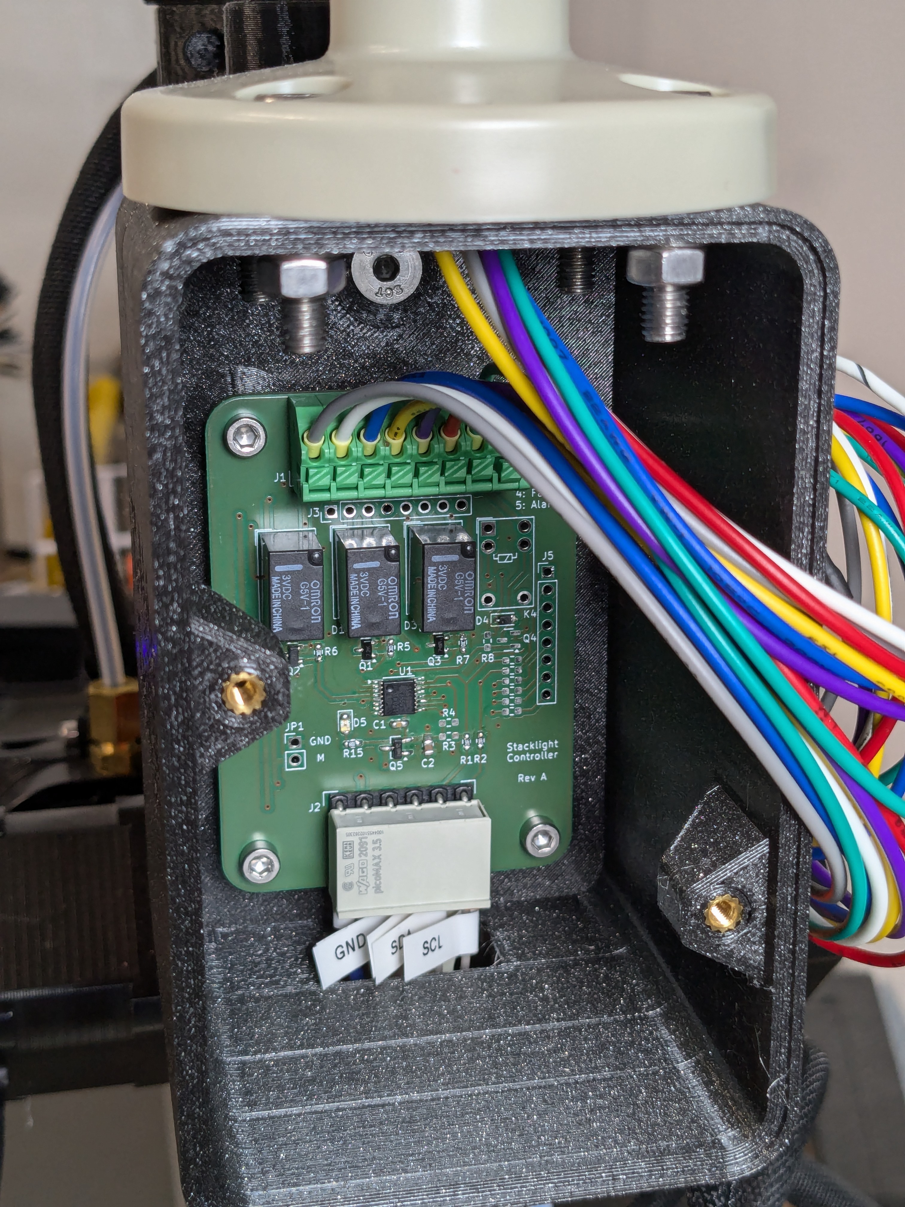
- Prepare the printer-side wiring with the Molex connector for the expansion port, the add-on-circuit for the 24V and the dupont pin for the GND. On the stacklight controller side, the wires terminate in the WAGO picoMAX connector. Check the wiring diagram for details.
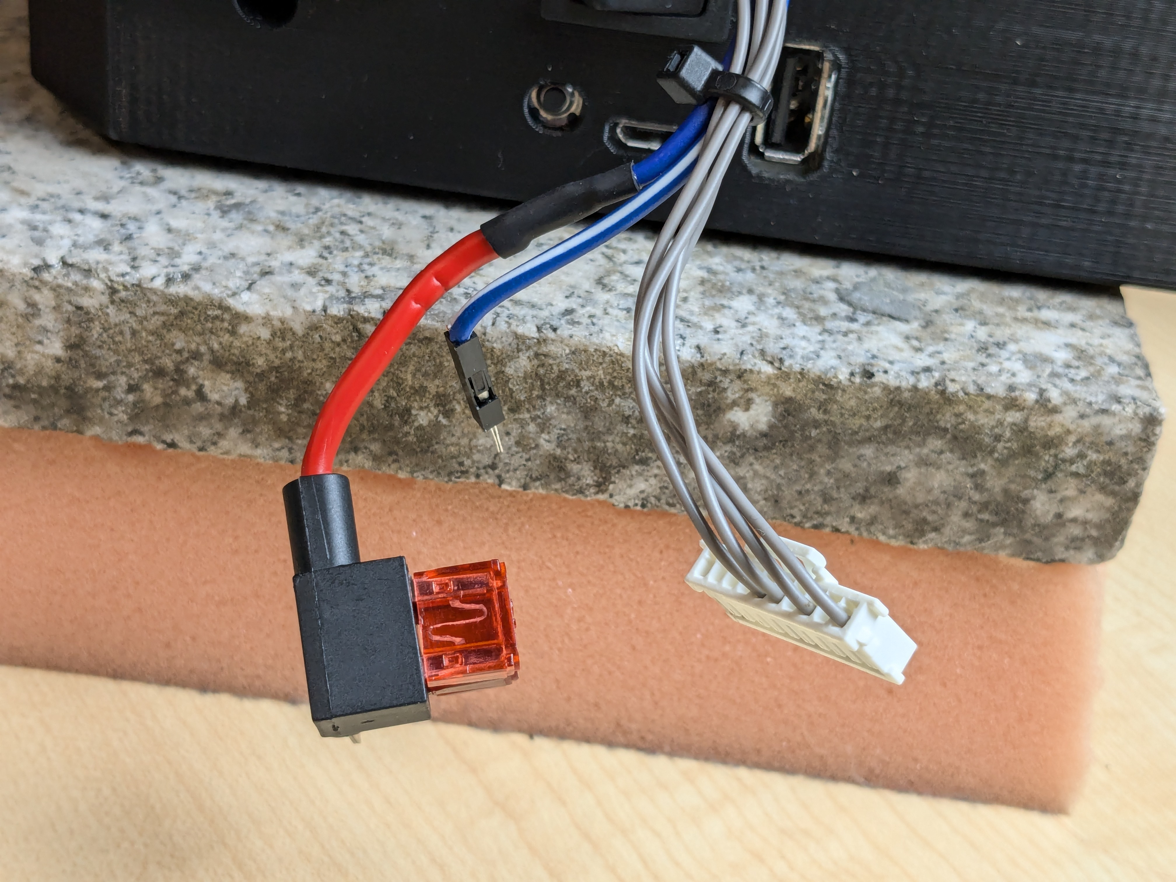
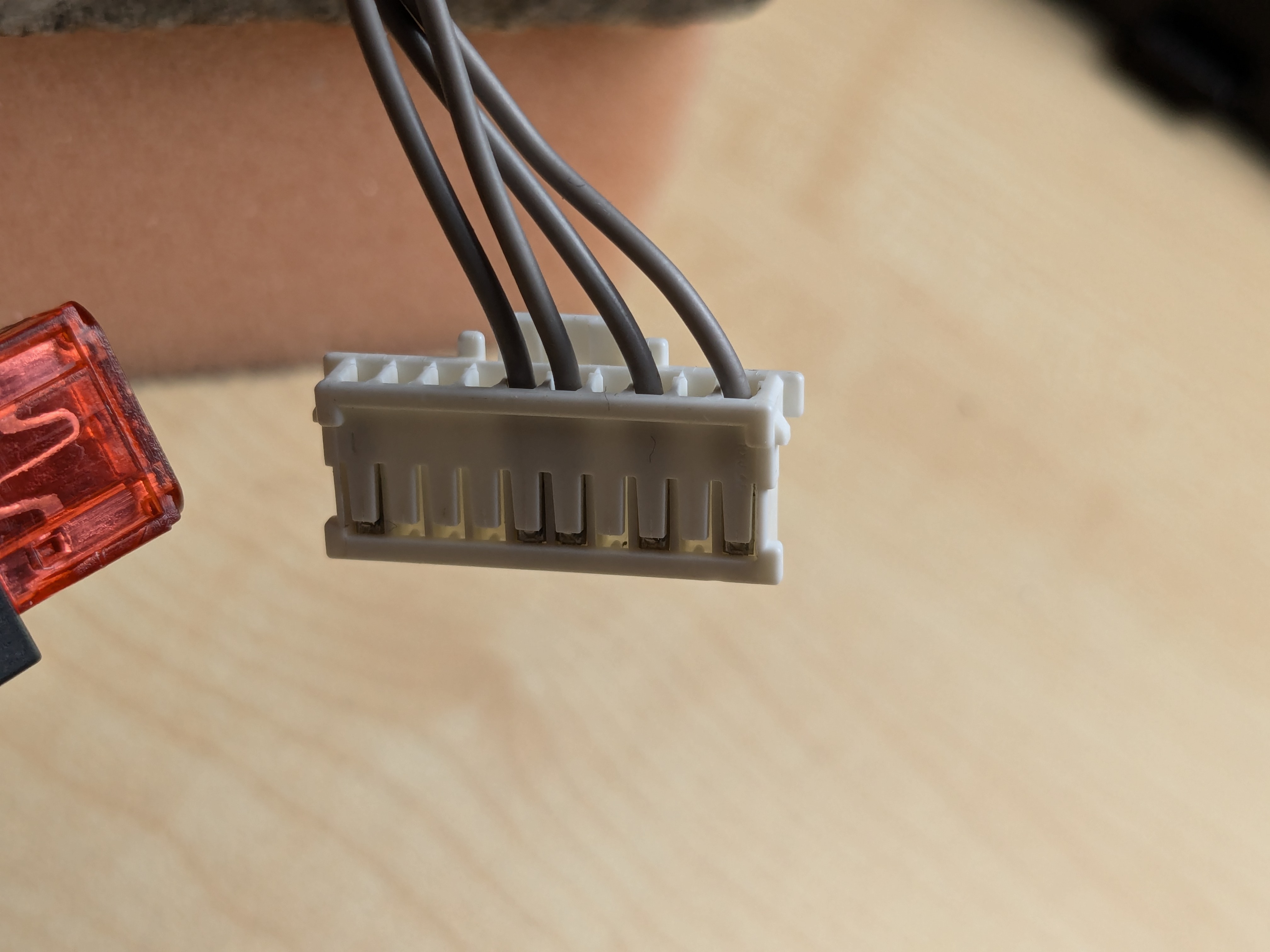
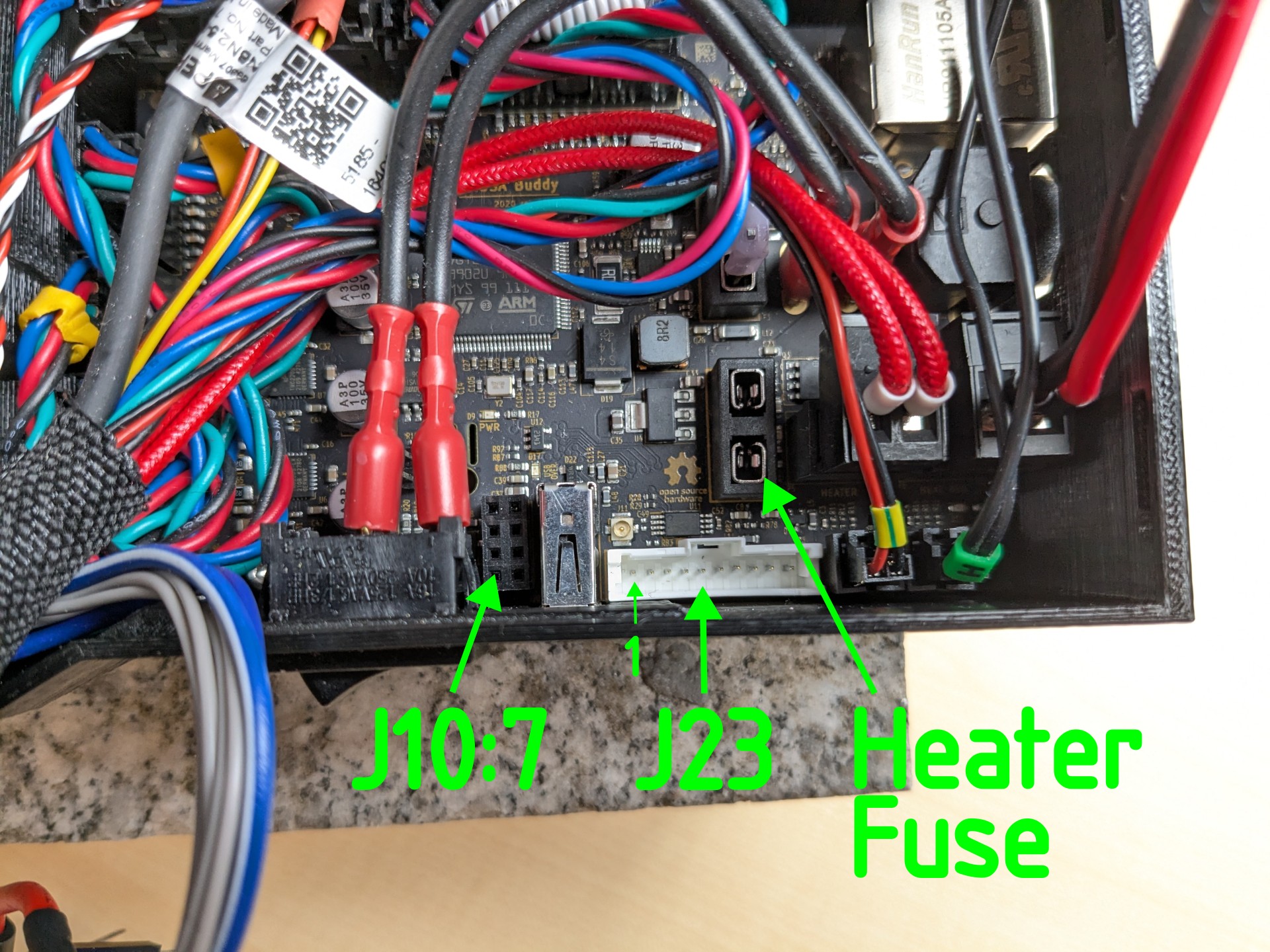
- Plug the connectors into the appropriate locations on the Prusa Mini+ board. Again, check the wiring diagram. Pull the heater fuse and place it into the add-on circuit plug. Here is an overview of the connector locations:
- With all the wires in place, it looks like this:
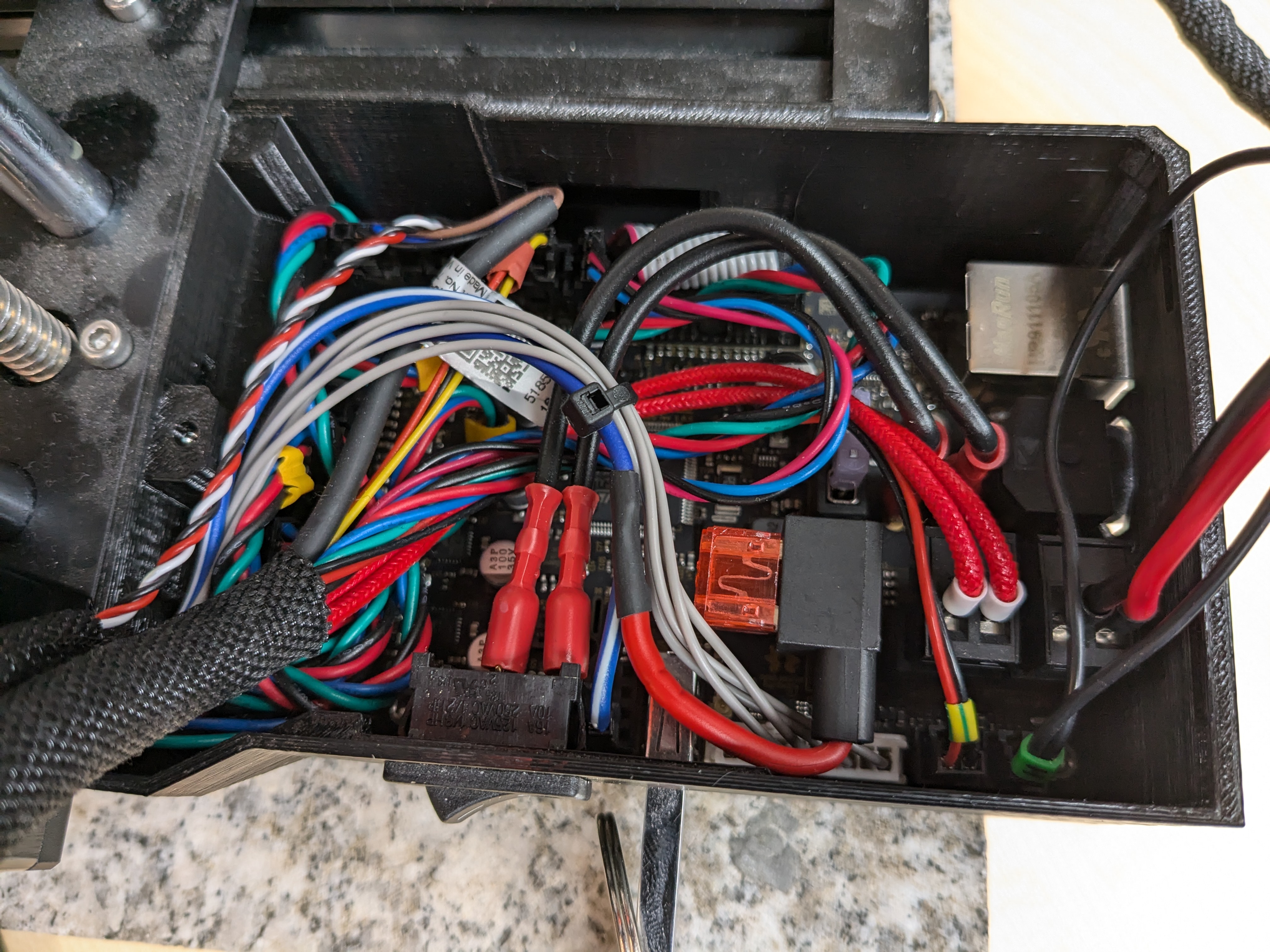
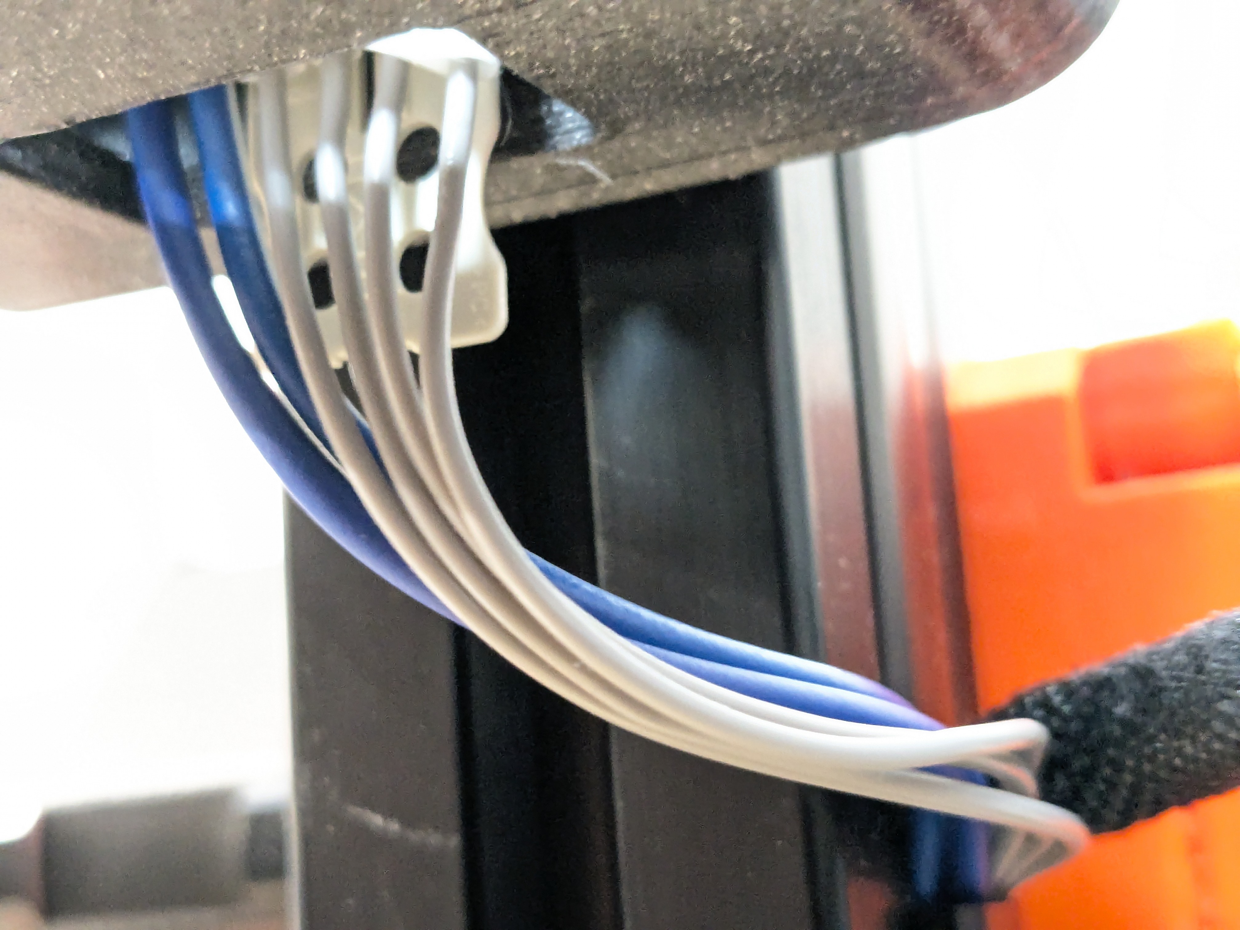
- Run the wires in the slot profile next to the existing stepper wires. Plug the picoMAX connector into the stacklight controller.
4 - Configuration
You are now ready to turn on the system. You will need to modify your printer profile a bit so the g-codes to control the stacklight are emitted. Here are the lines that need to be added (and some of the context lines that are there by default):
Start G-Code
G90 ; use absolute coordinates
M83 ; extruder relative mode; Stack Light Init
M260 A32
M260 B1 ; Output Register
M260 B1 ; Fault Off
M260 S
M260 B3 ; Configuration Register
M260 B0 ; All outputs
M260 S
M104 S170 ; set extruder temp for bed leveling
M140 S[first_layer_bed_temperature] ; set bed temp
End G-Code
G4 ; wait
M104 S0 ; turn off temperature
M190 R50 ; Wait for cooldown to a touchable temperature
; Stack Light Color Change
M260 A32
M260 B1 ; Output Register
M260 B3 ; Fault Off & Ready
M260 S
M140 S0 ; turn off heatbed
Color Change G-Code
; Stack Light Color Change
M260 A32
M260 B1 ; Output Register
M260 B3 ; Fault Off & Ready
M260 S
M600
; Stack Light Color Change
M260 A32
M260 B1 ; Output Register
M260 B1 ; Fault Off & Operate
M260 S
Pause Print G-Code
; Stack Light Color Change
M260 A32
M260 B1 ; Output Register
M260 B3 ; Fault Off & Ready
M260 S
M601
; Stack Light Color Change
M260 A32
M260 B1 ; Output Register
M260 B1 ; Fault Off & Operate
M260 S